01-75PAA-2-4-6 CH 10 EDITED FOR BR_2871025
This document was submitted by our user and they confirm that they have the consent to share it. Assuming that you are writer or own the copyright of this document, report to us by using this DMCA report button.
TECHNICAL MANUAL
ORGANIZATIONAL MAINTENANCE PROPELLER
NAVY MODELS P-3A, P-3B AND P-3C AIRCRAFT
N00421-98-D-1339
DISTRIBUTION STATEMENT C. Distribution authorized to U.S. Government agencies and their contractors to protect publications required for official use or for administrative or operational purposes only (1 May 2003). Other requests for this document shall be referred to Commander, Naval Air Systems Command (PMA−290), 47123 Buse Rd, Patuxent River, MD 20670-1547. DESTRUCTION NOTICE − For unclassified, limited documents, destroy by any method that will prevent disclosure of contents or reconstruction of the document.
Published by Direction of Commander, Naval Air Systems Command
Page Intentionally Left Blank
NOTICE
This information is furnished upon the condition that it or knowledge of its possession will not be released to another nation without specific authority from the Department of the Navy of the U.S.; that it will not be used for other than military purposes; that individual or corporate rights originating in the information, whether patented or not, will be respected and; that the information will be provided the same degree of security afforded it by the Department of Defense of the U.S. Regardless of any other markings on this document, it may not be declassified or downgraded without the written approval of the originating U.S. agency.
NAVAIR 01-75PAA-2-4.6 Page A
Change 10 − 1 March 2015 NUMERICAL INDEX OF EFFECTIVE WORK PACKAGES/PAGES
List of Current Changes Change 4 . . . . . . . . . . . . . . . . . . . . . . . . . . . 1 Apr 2009 Original . . . . . . . . . . . . . . . . . . . . . . . . . . . . 1 May 2003 Change 5 . . . . . . . . . . . . . . . . . . . . . . . . . 30 Jun 2009 (Inc. IRACs 1 - 18) Change 6 . . . . . . . . . . . . . . . . . . . . . . . . . 15 Jan 2011 RAC 21 . . . . . . . . . . . . . . . . . . . . . . . . . . . 10 Mar 2005 (Inc IRAC 26) (Inc. IRACs 19 - 20) Change 7 . . . . . . . . . . . . . . . . . . . . . . . . . . 1 May 2012 Change 1 . . . . . . . . . . . . . . . . . . . . . . . . . . 1 Mar 2006 (IRAC 27 Cancelled, Inc IRACs 28 - 29) (Inc. IRACs 22 - 23) Change 8 . . . . . . . . . . . . . . . . . . . . . . . . . . 1 Feb 2013 Change 2 . . . . . . . . . . . . . . . . . . . . . . . . . . . 1 Apr 2007 Change 9 . . . . . . . . . . . . . . . . . . . . . . . . . . . 1 Apr 2014 Change 3 . . . . . . . . . . . . . . . . . . . . . . . . . . 1 Jan 2008 Change 10 . . . . . . . . . . . . . . . . . . . . . . . . . 1 Mar 2015 (Inc IRACs 24 - 25) (Inc. IRACs 30 − 31) Only those work packages/pages assigned to the manual are listed in this index. Dispose of superseded and deleted work packages/pages. Superseded and deleted classified work packages/pages shall be destroyed in accordance with applicable regulations. If changed pages are issued to a work package, insert the changed pages in the applicable work package. The portion of text affected in a changed or revised work package is indicated by change bars or the change symbol “R” in the outer margin of each 0 column of text. Changes to illustrations are indicated by pointing hands or change bars, as applicable. WP Number
WP Number
Title
Title
005 00 Blade Inspection and Repair 006 00 Fluid System Maintenance Numerical Index of Effective 007 00 System Components Maintenance Work Packages/Pages 008 00 Front and Rear Spinner Removal TPDR List of Technical Publication and Installation Deficiency Reports Incorporated 008 01 Air Baffle Assembly, Disassembly HMWS Warnings Applicable to Hazardous and Repair Materials 009 00 Removal and Installation 001 00 Alphabetical Index 010 00 Propeller Control Maintenance 002 00 Introduction 011 00 Valve Housing 003 00 Description and Principles 012 00 Adjustment of Operation 013 00 Propeller Control Adjustment 004 00 General Maintenance and System 014 00 Propeller Control Linkage Rigging Checks Total number of pages in this manual is 284 consisting of the following: Title Page A
WP/Page No.
Change No.
Title . . . . . . . . . . . . . . . . . . . . . 10 A-C . . . . . . . . . . . . . . . . . . . . . . 10 TPDR-1 . . . . . . . . . . . . . . . . . . 10 TPDR-2 Blank . . . . . . . . . . . . 10 HMWS-1 . . . . . . . . . . . . . . . . . . 5 HMWS-2 - HMWS-3 . . . . . . . . 0 HMWS-4 . . . . . . . . . . . . . . . . . . 1 HMWS-5 . . . . . . . . . . . . . . . . . . 2
WP/Page No.
Change No.
HMWS-6 - HMWS-9 . . . . . . . . HMWS-10 . . . . . . . . . . . . . . . . . HMWS-11 . . . . . . . . . . . . . . . . . HMWS-12 Blank . . . . . . . . . . . 001 00 1 ....................... 2 Blank . . . . . . . . . . . . . . . . . 002 00
0 2 5 5 5 5
WP/Page No.
Change No.
1 ....................... 9 2 ....................... 0 3-5 .................... 9 6-8 .................... 0 9 ....................... 6 10 . . . . . . . . . . . . . . . . . . . . . 0 11 . . . . . . . . . . . . . . . . RAC 21 12 Blank . . . . . . . . . . RAC 21
NAVAIR 01-75PAA-2-4.6 Page B
Change 10 − 1 March 2015 NUMERICAL INDEX OF EFFECTIVE WORK PACKAGES/PAGES (Cont) WP/Page No.
Change No.
003 00 1 ....................... 9 2-6 .................... 0 7 ....................... 9 8 Blank . . . . . . . . . . . . . . . . . 9 9 - 11 . . . . . . . . . . . . . . . . . . . 0 12 Blank . . . . . . . . . . . . . . . . 0 13 - 19 . . . . . . . . . . . . . . . . . 0 20 Blank . . . . . . . . . . . . . . . . 0 21 . . . . . . . . . . . . . . . . . . . . . 0 22 Blank . . . . . . . . . . . . . . . . 0 23 - 25 . . . . . . . . . . . . . . . . . 0 26 Blank . . . . . . . . . . . . . . . . 0 27 . . . . . . . . . . . . . . . . . . . . . 0 28 Blank . . . . . . . . . . . . . . . . 0 29 - 32 . . . . . . . . . . . . . . . . . 0 004 00 1 - 2 . . . . . . . . . . . . . . . . . . . 10 3 ....................... 0 4 ....................... 2 5 ....................... 3 6 ....................... 1 7 ....................... 0 8 . . . . . . . . . . . . . . . . . . . . . . 10 9 ....................... 9 10 - 14 . . . . . . . . . . . . . . . . 10 15 - 17 . . . . . . . . . . . . . . . . . 6 18 Blank . . . . . . . . . . . . . . . . 6 19 . . . . . . . . . . . . . . . . . . . . . 6 20 Blank . . . . . . . . . . . . . . . . 6 21 . . . . . . . . . . . . . . . . . . . . . 8 22 . . . . . . . . . . . . . . . . . . . . . 6 23 - 24 Added . . . . . . . . . . . 6 005 00 1 ....................... 9 2-5 .................... 0 6-7 .................... 2 8-9 .................... 0
WP/Page No.
Change No.
10 . . . . . . . . . . . . . . . . . . . . . 1 11 - 16 . . . . . . . . . . . . . . . . . . 0 17 - 18 . . . . . . . . . . . . . . . . . 2 19 - 22 . . . . . . . . . . . . . . . . . 0 23 . . . . . . . . . . . . . . . . . . . . . 9 24 Blank . . . . . . . . . . . . . . . . 9 006 00 1 ....................... 9 2-3 .................... 0 4 ....................... 9 5 ....................... 0 6 ....................... 2 7 ....................... 1 8 ....................... 2 9 - 10 . . . . . . . . . . . . . . . . . . . 1 11 . . . . . . . . . . . . . . . . . . . . . . 0 12 . . . . . . . . . . . . . . . . . . . . . 9 13 - 14 . . . . . . . . . . . . . . . . . 0 15 - 19 . . . . . . . . . . . . . . . . . 2 20 Blank . . . . . . . . . . . . . . . . 2 007 00 1 ....................... 9 2-3 .................... 0 4 ....................... 9 5 ....................... 0 6 ....................... 2 7 ....................... 1 8 - 12 . . . . . . . . . . . . . . . . . . . 0 13 . . . . . . . . . . . . . . . . . . . . . 7 14 - 16 . . . . . . . . . . . . . . . . . 0 17 . . . . . . . . . . . . . . . . . . . . . 1 18 . . . . . . . . . . . . . . . . . . . . . 7 008 00 1-2 .................... 6 3-6 .................... 0 008 01 1-6 .................... 5 009 00 1 . . . . . . . . . . . . . . . . . . . . . . 10
WP/Page No.
Change No.
2 ....................... 5 3 ....................... 0 4 ....................... 9 5-9 .................... 0 10 Blank . . . . . . . . . . . . . . . . 0 11 . . . . . . . . . . . . . . . . . . . . . . 8 12 . . . . . . . . . . . . . . . . . . . . . 0 13 . . . . . . . . . . . . . . . . . . . . 10 14 . . . . . . . . . . . . . . . . . . . . . 9 15 . . . . . . . . . . . . . . . . . . . . . 9 16 . . . . . . . . . . . . . . . . . . . . . 6 17 . . . . . . . . . . . . . . . . . . . . . 7 18 - 21 . . . . . . . . . . . . . . . . . 0 22 . . . . . . . . . . . . . . . . . . . . . 1 23 . . . . . . . . . . . . . . . . . . . . . 0 24 - 25 . . . . . . . . . . . . . . . . . 9 26 . . . . . . . . . . . . . . . . . . . . . 9 27 . . . . . . . . . . . . . . . . . . . . . 0 28 . . . . . . . . . . . . . . . . . . . . . 7 29 . . . . . . . . . . . . . . . . . . . . . 3 30 Blank . . . . . . . . . . . . . . . . 3 31 . . . . . . . . . . . . . . . . . . . . . 2 32 . . . . . . . . . . . . . . . . . . . . . 0 33 . . . . . . . . . . . . . . . . . . . . . 9 34 Blank . . . . . . . . . . . . . . . . 9 35 Deleted . . . . . . . . . . . . . . 5 36 Blank Deleted . . . . . . . . 5 010 00 1 ....................... 9 2-3 .................... 0 4 Blank . . . . . . . . . . . . . . . . . 0 5 ....................... 8 6 ....................... 0 7 ....................... 9 8 - 15 . . . . . . . . . . . . . . . . . . . 0 16 . . . . . . . . . . . . . . . RAC 21 17 - 19 . . . . . . . . . . . . . . . . . 0 20 Blank . . . . . . . . . . . . . . . . 0 21 . . . . . . . . . . . . . . . . . . . . . 7 22 . . . . . . . . . . . . . . . . . . . . . 9
NAVAIR 01-75PAA-2-4.6 Page C
Change 10 − 1 March 2015 NUMERICAL INDEX OF EFFECTIVE WORK PACKAGES/PAGES (Cont) WP/Page No.
Change No.
011 00 1 . . . . . . . . . . . . . . . . . . . . . . 10 2 . . . . . . . . . . . . . . . . . RAC 21 3 ....................... 0 4 Blank . . . . . . . . . . . . . . . . . 0 5-7 .................... 0 8 Blank . . . . . . . . . . . . . . . . . 0 9 ....................... 9 10 . . . . . . . . . . . . . . . . . . . . . 7 11 - 13 . . . . . . . . . . . . . . . . . . 0 14 . . . . . . . . . . . . . . . . . . . . . 1 15 . . . . . . . . . . . . . . . . . . . . . 0 16 . . . . . . . . . . . . . . . . . . . . 10 17 - 27 . . . . . . . . . . . . . . . . . 0
WP/Page No.
Change No.
28 Blank . . . . . . . . . . . . . . . . 0 012 00 1 . . . . . . . . . . . . . . . . . . . . . . 10 2 ....................... 0 3 ....................... 1 4 - 12 . . . . . . . . . . . . . . . . . . . 0 13 . . . . . . . . . . . . . . . . . . . . 10 14 Blank . . . . . . . . . . . . . . . 10 013 00 1 . . . . . . . . . . . . . . . . . . . . . . 10 2 . . . . . . . . . . . . . . . . . . . . . . 10 3 ....................... 0 4 Blank . . . . . . . . . . . . . . . . . 0 5 - 9 . . . . . . . . . . . . . . . . . . . 10
WP/Page No.
Change No.
10 Blank . . . . . . . . . . . . . . . 10 014 00 1 . . . . . . . . . . . . . . . . . . . . . . 10 2 ....................... 7 3 ....................... 0 4 - 4A . . . . . . . . . . . . . . . . . . 4 4B Blank . . . . . . . . . . . . . . . . 4 5 ....................... 7 6 Blank . . . . . . . . . . . . . . . . . 7 7 ....................... 0 8 . . . . . . . . . . . . . . . . . . . . . . 10 9 ....................... 0 10 Blank . . . . . . . . . . . . . . . . 0 11 - 12 . . . . . . . . . . . . . . . . . . 0
NAVAIR 01-75PAA-2-4.6 TPDR-1/(TPDR-2 Blank)
Change 10 − 1 March 2015
LIST OF TECHNICAL PUBLICATION DEFICIENCY REPORTS INCORPORATED ORGANIZATIONAL MAINTENANCE PROPELLER
Identification No./ QA Sequence No. R09600−14−0019 R09618−15−0011 N09047−14−0074 N09047−14−0075 N65886−15−7311 N62606−14−0003
Location ................................ ................................ ................................ ................................ ................................ ................................
WP 004 00, Pg. 1, 2, 8, 10−14 WP 009 00, Pg. 13 WP 011 00, Pg. 16 WP 011 00, Pg. 16 WP 013 00, Pg. 2 WP 013 00, Pg. 5−9
NAVAIR 01-75PAA-2-4.6
HMWS-1
Change 5 − 30 June 2009 ⎯⎯⎯⎯⎯⎯⎯⎯⎯⎯⎯⎯⎯⎯⎯⎯⎯⎯⎯⎯⎯⎯⎯⎯⎯⎯⎯⎯⎯⎯⎯⎯⎯⎯⎯⎯⎯⎯⎯⎯⎯⎯⎯⎯⎯⎯⎯⎯⎯⎯
WARNINGS APPLICABLE TO HAZARDOUS MATERIALS ⎯⎯⎯⎯⎯⎯⎯⎯⎯⎯⎯⎯⎯⎯⎯⎯⎯⎯⎯⎯⎯⎯⎯⎯⎯⎯⎯⎯⎯⎯⎯⎯⎯⎯⎯⎯⎯⎯⎯⎯⎯⎯⎯⎯⎯⎯⎯⎯⎯⎯ 1. INTRODUCTION. 2. Warnings for hazardous materials listed in this manual are designed to warn personnel of hazards associated with such items when they come in contact with them by actual use. Additional information related to hazardous materials is provided in OPNAVINST 5100.23, Navy Occupational Safety and Health (NAVOSH) Program manual, NAVSUPINST 5100.27, Navy Hazardous Material Control Program, and the DOD 6050.5, Hazardous Materials Information System (HMIS) series publications. For each hazardous material used within the Navy, a material safety data sheet (MSDS) is required to be provided and available for review by users. Consult your local safety and health staff concerning any question on hazardous chemicals, MSDSs, personal protective equipment requirements, and appropriate handling and emergency procedures and disposal guidance.
3. Complete warnings for hazardous materials referenced in this manual are identified by use of an icon, nomenclature and specification or part number of the material, and a numeric identifier. The numeric identifiers have been assigned to the hazardous materials in the order of their appearance in the manual. Each hazardous material is assigned only one numeric identifier. Repeated use of a specific hazardous material references the numeric identifier assigned at its initial appearance. The approved icons and their applications are shown in Figure 1. 4. In the text of the manual, the caption “warning” will not be used for hazardous materials. Such warnings will be identified by an icon and numeric identifier. The material nomenclature will also be provided. The user is directed to refer to the corresponding numeric identifier for the complete warning applicable to the hazardous material as shown in Table 1.
NAVAIR 01-75PAA-2-4.6
HMWS-2
EXPLANATION OF HAZARD SYMBOLS
CHEMICAL THE SYMBOL OF A DROP OF A LIQUID BURNING A HAND SHOWS A MATERIAL THAT CAUSES BURNS TO HUMAN SKIN OR TISSUE.
EXPLOSION THIS RAPIDLY EXPANDING SYMBOL SHOWS THAT THE MATERIAL MAY EXPLODE IF SUBJECTED TO HIGH TEMPERATURE, SOURCES OF IGNITION, OR HIGH PRESSURE.
EYE PROTECTION THE SYMBOL OF A PERSON WEARING GOGGLES SHOWS A MATERIAL THAT CAN INJURE YOUR EYES.
FIRE THE SYMBOL OF A FIRE SHOWS THAT A MATERIAL CAN IGNITE AND BURN YOU.
POISON THE SYMBOL OF SKULL AND CROSSBONES SHOWS THAT A MATERIAL IS POISONOUS OR IS A DANGER TO LIFE.
VAPOR HAZARD THE SYMBOL OF A HUMAN FIGURE IN A CLOUD SHOWS THAT BREATHING THIS MATERIAL CAN PRESENT A HEALTH HAZARD.
Figure 1. Icons for Hazardous Materials and Examples of Application
NAVAIR 01-75PAA-2-4.6
HMWS−3
Table 1. Hazardous Materials Warnings Index
Material
Warning
1
SOLVENT, DRY CLEANING, P-D-680, TYPE III
This high flash point dry cleaning solvent is toxic, a skin irritant and an inhalation hazard. Keep away from heat, sparks and open flames. Do not smoke, eat or drink when using solvent. Use in well-ventilated area. Avoid prolonged breathing of vapor and skin contact. Skin contact may cause defatting and irritation of eyes, nose, throat and skin. Inhalation of high concentration of vapor may cause drowsiness and irritation of respiratory tract, which can cause dermatitis, irritated nose and throat and dizziness. Ingestion will cause gastro-intestinal irritation. Wear approved gloves, goggles, coveralls and respirator. Inhalation: Remove to fresh air if vapor causes drowsiness. Skin contact: Flush with water; remove solvent-saturated clothing. Get medical attention.
2
SOLVENT, DRY CLEANING, P-D-680, TYPE II
Dry cleaning solvent is flammable, toxic, a skin irritant and an inhalation hazard. Keep away from heat, sparks and open flames. Do not use synthetic cloth for wiping with dry cleaning solvent. Metal containers of solvent shall be grounded to prevent sparking and fires. Do not smoke, eat or drink when using solvent. Use in well-ventilated area. Avoid prolonged breathing of vapor and skin contact, which can cause dermatitis, irritated nose and throat and dizziness. Ingestion will cause gastro-intestinal irritation. Wear approved gloves, goggles, coveralls and respirator. Inhalation: Remove to fresh air if vapor causes dizziness. Skin contact: Flush with water; remove solvent-saturated clothing. Get medical attention.
3
METHYL ETHYL KETONE, TT-M-261
Methyl ethyl ketone is flammable and toxic. Keep away from heat, sparks and open flames. Use in well-ventilated area. Wear splash-proof goggles, solvent resistant gloves and coveralls. Eye contact: Flush with water; get medical attention.
4
ADHESIVE, RUBBER, BOSTIK 1007
Rubber adhesive is flammable and toxic. Keep product and its vapor away from heat, sparks and open flames. Use in well-ventilated area. Avoid prolonged breathing of vapor. Avoid contact with eyes and skin. Keep container tightly closed when not in use.
HMWS-4
NAVAIR 01-75PAA-2-4.6 Change 1 − 1 March 2006
Table 1. Hazardous Materials Warnings (Continued) Index
Material
Warning
5
ADHESIVE, RUBBER, BOSTIK 1096
Rubber adhesive is flammable and toxic. Keep product and its vapor away from heat, sparks and open flames. Use in well-ventilated area. Avoid prolonged breathing of vapor. Avoid contact with eyes and skin. Keep container tightly closed when not in use.
6
SEALANT, EC801/801A
Sealant is toxic and flammable. Keep away from heat, sparks and open flames. Use in well-ventilated area. Avoid prolonged breathing of vapor and eye and skin contact. Keep container tightly closed when not in use.
7
ALCOHOL, ISOPROPYL (IPA), TT-I-735
Isopropyl alcohol is flammable and toxic. Avoid breathing vapor. Use in well-ventilated area. Keep away from heat, sparks or open flames. Wear splash-proof goggles, solvent resistant gloves and other protective gear. Eye contact: Flush with water; get medical attention.
8
CHEMICAL CONVERSION MATERIAL, MIL-DTL-81706, TYPE 1
Chemical conversion material is a strong oxidizer which supports combustion to skin, eyes and mucous membranes. It can also cause irritation and ulcers of the nasal septum as well as irritation and damage to the respiratory system. Wear neoprene gloves, chemical goggles and rubber apron during conversion coating operation. Wear respirator when handling the material in powder form and during spraying operation.
9
SEALANT, EC-776
Sealant is toxic and flammable. Keep away from heat, sparks and open flames. Use in well-ventilated area. Avoid prolonged breathing of vapor and eye and skin contact. Keep container tightly closed when not in use.
HMWS−5
NAVAIR 01-75PAA-2-4.6 Change 2 − 1 April 2007
Table 1. Hazardous Materials Warnings (Continued) Index
Material
Warning
10
ACTIVATOR, BOSCODUR NO. 9
Boscodur No. 9 is compounded in inflammable solvents. Keep away from heat, sparks and open flames. Use in well-ventilated area. Avoid prolonged breathing of vapor. Avoid prolonged or repeated contact with skin.
11
SOLDER, MECHANICAL
The lead contained in solder can be the source of lead oxide that can rub off onto a person’s hand from a soldered joint. Lead oxide is a poison that is not thrown off by the body and can therefore accumulate over years. Wash hands with soap and water after use and before eating, drinking or smoking.
12
ADHESIVE EA9396
Excessive or repeated skin contact with anaerobic adhesive/sealants may cause skin irritation in sensitive persons. In case of contact with sensitive skin, remove promptly by washing with soap and water. In case of skin reaction, discontinue contact with product. If skin reaction persists, get medical attention. To avoid skin contact, use the applicator nozzle provided.
13
COMPOUND, CLEANING, MIL-C-43616
This cleaning compound is an alkaline cleaner. Composition may vary according to manufacturers formulations. It is typically caustic to skin and eyes. Avoid breathing vapor. Eye contact: Immediately flush with water; get medical attention.
14
COMPOUND, CORROSION PREVENTIVE, MIL-C-16173
Corrosion preventive compound is flammable, toxic and has harmful vapor. Keep container tightly closed when not in use. Keep away from heat, sparks and open flames. Use in well-ventilated area. Wear chemical splash-proof goggles and gloves. Avoid contact with clothing, eyes and skin. Wash hands thoroughly with soap and water after use.
HMWS-6
NAVAIR 01-75PAA-2-4.6
Table 1. Hazardous Materials Warnings (Continued) Index
Material
Warning
15
REMOVER, EPOXY PAINT, MIL-R-25134
Strippers containing phenols and methylene chloride are toxic, corrosive and an inhalation hazard. Use in well-ventilated area. Prolonged breathing of vapor and repeated skin contact can have a toxic/corrosive effect, skin blisters, dermatitis, eye, nose and throat irritation, dizziness and headache. Do not smoke, eat or drink when using stripper. Wear approved respirators or eye and face protection, rubber gloves, wet weather suit and protective boot covers. Remove clothing saturated with stripper. Eye or skin contact: Flush with water; get medical attention.
16
FLUID, HYDRAULIC, MIL-H-83282
Hydraulic fluid is flammable, toxic and produces toxic vapor if heated. Keep container tightly closed when not in use. Keep away from heat, sparks and open flames. Use in well-ventilated area. Wear chemical splash-proof goggles and gloves. Avoid contact with clothing, eyes and skin. Wash hands thoroughly with soap and water after use.
17
PETROLATUM, VV-L-236
Petrolatum is toxic and heated can emit harmful fumes. Avoid contact with skin, eyes and clothing. Wash hands with soap and water after use.
18
COMPOUND, WATER PROOFING, GLYPTAL LACQUER, GE2606
Lacquer paint is highly flammable, toxic and an inhalation hazard. Keep away from heat, sparks and open flames. Wear goggles, respirator, rubber gloves and coveralls during all paint mixing and spraying operations. Avoid prolonged breathing of vapor. Prolonged or repeated skin contact can have a toxic effect on affected skin areas.
19
THINNER, GED519
Thinner is flammable and toxic. Keep away from heat, sparks and open flames. Use in well-ventilated area. Wear solvent-resistant gloves, splash-proof goggles and coveralls. Eye contact: Flush with water; get medical attention.
HMWS−7
NAVAIR 01-75PAA-2-4.6
Table 1. Hazardous Materials Warnings (Continued) Index
Material
Warning
20
AIR, COMPRESSED
When using compressed air for any cleaning or drying operation, do not exceed 30 psig at the nozzle. Eyes can be permanently damaged by contact with liquid or large particles propelled by compressed air. Inhalation of air blown particles or solvent vapor can damage lungs. When using air for drying or cleaning at an air-exhausted workbench, wear approved goggles or face shield. When using air for drying or cleaning at an unexhausted workbench, wear approved respirator and goggles.
21
CLEANER, LUBRICANT, PRESERVATIVE, MIL-L-63460
Preservative lubricant cleaner is toxic and a strong irritant. It is flammable and produces toxic vapor if heated. Keep away from heat, sparks and open flames. Use in well-ventilated area. Ingestion: Do not induce vomiting; get medical attention. Eye contact: Flush with cold water; get medical attention. Skin contact: Wash with soap and water. Inhalation: Remove to fresh air; get medical attention. Wash hands with soap and water after use and before eating, drinking or smoking.
22
GREASE, MIL-G-23827
MIL−PRF−23827 Aircraft and Instrument Grease is toxic and an irritant to the eyes and skin. Avoid prolonged contact. Wear: Safety glasses and oil resistant gloves. Consult the applicable Material Safety Data Sheet (MSDS) and local Occupational Safety and Health (OSH) regulations for appropriate safety precautions.
23
LUBRICANT, SOLID FILM, MIL-L-23398
Solid film lubricant, in the liquid or spray as-applied form, is flammable, toxic and contains a solvent whose fumes are toxic. When heated above 700°F, the dried, cured solid film can emit harmful fumes. Keep away from heat, sparks and open flames. Do not machine, abrade or grind solid film in such a way as to put particles into breathing air. Use in well-ventilated area. Avoid contact with skin, eyes and clothing. Avoid breathing vapor. Wear chemical splash-proof goggles and gloves. Wash hands with soap and water after use and before eating, drinking or smoking.
24
GREASE, AIRCRAFT AND INSTRUMENT, MIL-G-81322
Grease is toxic and when heated can emit harmful fumes. Avoid contact with skin, eyes and clothing. Wash hands with soap and water after use.
HMWS-8
NAVAIR 01-75PAA-2-4.6
Table 1. Hazardous Materials Warnings (Continued) Index
Material
Warning
25
PRIMER, ZINC CHROMATE, TT-P-1757
Zinc chromate primer is flammable, toxic and an inhalation hazard. Keep away from heat, sparks and open flames. Wear goggles or face shield, air-supplied or cartridge respirator, rubber gloves and coveralls during all primer mixing and spraying operations. Primer contains zinc chromate corrosion inhibiting pigments. Airborne mist is toxic. Avoid prolonged breathing of vapor. Prolonged or repeated skin contact can have a toxic effect on affected skin areas.
26
ACETONE, O-A-51
Acetone is flammable. Do not breathe vapors. Do not use near heat, vapors, open flames, or any source of ignition. Use only in a well-ventilated area. Do not allow contact with skin or eyes. Protection: gloves and goggles.
27
COMPOUND, SEALING, POLYSULFIDE, MIL-S-8802, TYPE II, FOR BRUSH APPLICATION
The base component contains methyl ethyl ketone and toluene solvents. Use in well-ventilated area. Avoid repeated or prolonged breathing of vapor and skin contact. Use rubber gloves and goggles. Skin contact: Apply lanolin-based hand cream. Wash hands with soap and water after used and before eating, drinking or smoking. Consult the Material Safety Data Sheet for additional health and safety information.
28
SEALANT, PROSEAL 894
29
ADHESIVE, EC 3524
PRO−SEAL 894, Sealant is toxic, flammable and may cause skin or eye irritation. Avoid breathing of vapors and prolonged or repeated skin contact. Keep away from heat, sparks and open flame. Protection: gloves and goggles.
Adhesive, EC 3524, is flammable and may cause skin and eye irritation. Protection: gloves and goggles.
HMWS−9
NAVAIR 01-75PAA-2-4.6
Table 1. Hazardous Materials Warnings (Continued) Index
Material
Warning
30
EPOXY RESIN, EPON 834
31
EPOXY RESIN, EPON 828
32
ADHESIVE, C−14
Adhesive, C−14. may cause eye or skin irritation. Protection: gloves and goggles.
33
LACQUER, TT−L−20
Cellulose Nitrate Lacquer, TT−L−20, is toxic and flammable. Avoid contact with skin and eyes. Avoid breathing vapors. Remove and wash contaminated clothing before re−use. Do not take internally. Protection: gloves and goggles.
34
SEALANT, PR1826−B1/2
SEALANT, PR1826−B1/2, Sealing compound may cause eye and skin irritation upon overexposure. Use in well ventilated area and avoid breathing vapors. Consult the applicable Material Safety Data Sheet (MSDS) and local Occupational Safety and Health (OSH) regulations for appropriate safety precautions. Protection: gloves and goggles.
Epoxy Resin, EPON 834, is flammable and may cause irritation to the skin and eyes. Protection: gloves and goggles.
Epoxy Resin Adhesive, EPON 828, is toxic and flammable. Avoid contact with skin and eyes. Use in well ventilated area and avoid breathing vapors. Wash hands thoroughly after each use. Protection: gloves and goggles.
HMWS-10
NAVAIR 01-75PAA-2-4.6 Change 2 − 1 April 2007
Table 1. Hazardous Materials Warnings (Continued) Index
35
Material
LACQUER, TT−L−32
36 COMPOUND, SEALING, MIL−PRF−8516
37
EPOXY ADHESIVE EPON 828
38
DIETHYLENETRIAMINE O−D−1271
Warning
Cellulose Nitrate Lacquer, TT−L−20, is toxic and flammable. Avoid contact with skin and eyes. Avoid breathing vapors. Remove and wash contaminated clothing before re−use. Do not take internally. Protection: gloves and goggles.
Polysulfide Rubber Sealing Compound, MIL−PRF−8516, is toxic. Avoid contact with skin and eyes. Avoid breathing vapors. Consult the applicable Material Safety Data Sheet (MSDS) and local Occupational Safety and Health (OSH) regulations for appropriate safety precautions. Protection: gloves and goggles.
Epoxy Adhesive Epon 828, causes irritation to skin and eyes and possible allergic reactions. Prolonged and repeated contact may cause sensitization which will result in allergic reactions. Avoid breathing vapor. Eye contact: Flush with water for 15 minutes. Skin contact: Wash with soap and water. Do not use solvents. Remove soiled clothing and wash before reuse. If irritation persists, get medical attention.
Diethylenetriamine O−D−1271 (technical grade), is toxic and flammable. Avoid contact with skin and eyes. Use in well ventilated area and avoid breathing vapors. Wash hands thoroughly after each use. Close container after usage. Store in a cool, dry and well ventilated area. Avoid contact with strong oxidizing agents. Protection: rubber gloves, chemical goggles and protective skin compound; respirator with organic vapor cartridge required in poorly ventilated areas.
NAVAIR 01-75PAA-2-4.6
HMWS-11/(12 blank)
Change 5 − 30 June 2009
Table 1. Index
Hazardous Materials Warnings (Continued)
Material
Warning
PETROLEUM SOLVENT, AMS3160
Cleaning Solvent AMS 3160, is a high flash point dry cleaning solvent and is toxic, a skin irritant and an inhalation hazard. Keep away from heat, sparks and open flames. Do not smoke, eat or drink when using solvent. Use in well−ventilated area. Avoid prolonged breathing of vapor and skin contact. Skin contact may cause defatting and irritation of eyes, nose, throat and skin. Inhalation of high concentration of vapor may cause drowsiness and irritation of respiratory tract, which can cause dermatitis, irritated nose and throat and dizziness. Ingestion will cause gastrointestinal irritation. Wear approved gloves, goggles, coveralls and respirator. Inhalation: Remove to fresh air if vapor causes drowsiness. Skin contact: Flush with water; remove solvent−saturated clothing. Get medical attention.
40
ASSEMBLY FLUID, MOBIL OR ULTRA CHEM 1
Assembly Fluid, Mobile or Ultra Chem 1, may cause irritation of the skin and eyes upon overexposure. Protection: chemical goggles and protective gloves.
41
AIRCRAFT EXTERIOR CLEANING COMPOUND MIL−PRF−85570
Aircraft Exterior Cleaning Compound, MIL−PRF−85570, Type I through V, is irrating to the eyes and skin. Proloinged contact may cause dermatitis. Protection: Chemical splashproof goggles and faceshield, gloves and good ventilation.
42
ALIPHATIC NAPHTHA TT−N−95
Naphtha, Aliphatic, TT−N−95 is flammable and can irritate skin and eyes. Avoid contact. Overexposure to vapors can cause dizziness, headache and other central nervous system effects. Avoid breathing vapors. Use with adequate ventilation. Wear nitrile gloves and safety glasses.
39
NAVAIR 01-75PAA-2-4.6
001 00
Change 5 − 30 June 2009
Page 1/(2 Blank)
ALPHABETICAL INDEX ORGANIZATIONAL MAINTENANCE PROPELLER
Title Adjustment . . . . . . . . . . . . . . . . . . . . . . . . . . . . . . . . . . . . . . . . . . . . . . . . . . . . . . . . . . . . . . . . . . . . . . . . . . . . . . Air Baffle Assembly, Disassembly and Repair . . . . . . . . . . . . . . . . . . . . . . . . . . . . . . . . . . . . . . . . . . . . . . . . Blade Inspection and Repair . . . . . . . . . . . . . . . . . . . . . . . . . . . . . . . . . . . . . . . . . . . . . . . . . . . . . . . . . . . . . . . Description and Principles of Operation . . . . . . . . . . . . . . . . . . . . . . . . . . . . . . . . . . . . . . . . . . . . . . . . . . . . . Fluid System Maintenance . . . . . . . . . . . . . . . . . . . . . . . . . . . . . . . . . . . . . . . . . . . . . . . . . . . . . . . . . . . . . . . . Front and Rear Spinner Removal and Installation . . . . . . . . . . . . . . . . . . . . . . . . . . . . . . . . . . . . . . . . . . . . . General Maintenance and System Checks . . . . . . . . . . . . . . . . . . . . . . . . . . . . . . . . . . . . . . . . . . . . . . . . . . Introduction . . . . . . . . . . . . . . . . . . . . . . . . . . . . . . . . . . . . . . . . . . . . . . . . . . . . . . . . . . . . . . . . . . . . . . . . . . . . . . List of Technical Publication Deficiency Reports Incorporated . . . . . . . . . . . . . . . . . . . . . . . . . . . . . . . . . . Propeller Control Adjustment . . . . . . . . . . . . . . . . . . . . . . . . . . . . . . . . . . . . . . . . . . . . . . . . . . . . . . . . . . . . . . Propeller Control Linkage Rigging . . . . . . . . . . . . . . . . . . . . . . . . . . . . . . . . . . . . . . . . . . . . . . . . . . . . . . . . . . Propeller Control Maintenance . . . . . . . . . . . . . . . . . . . . . . . . . . . . . . . . . . . . . . . . . . . . . . . . . . . . . . . . . . . . . Removal and Installation . . . . . . . . . . . . . . . . . . . . . . . . . . . . . . . . . . . . . . . . . . . . . . . . . . . . . . . . . . . . . . . . . . System Components Maintenance . . . . . . . . . . . . . . . . . . . . . . . . . . . . . . . . . . . . . . . . . . . . . . . . . . . . . . . . . Valve Housing . . . . . . . . . . . . . . . . . . . . . . . . . . . . . . . . . . . . . . . . . . . . . . . . . . . . . . . . . . . . . . . . . . . . . . . . . . . Warnings Applicable to Hazardous Materials . . . . . . . . . . . . . . . . . . . . . . . . . . . . . . . . . . . . . . . . . . . . . . . . .
WP Number 012 00 008 01 005 00 003 00 006 00 008 00 004 00 002 00 TPDR 013 00 014 00 010 00 009 00 007 00 011 00 HMWS
NAVAIR 01-75PAA-2-4.6
002 00
Change 9 − 1 April 2014
Page 1
INTRODUCTION PROPELLER 1.
PURPOSE AND SCOPE.
2. PURPOSE. The purpose of this manual is to provide general information, and a source of essential data for maintenance of P-3A, P-3B and P-3C aircraft propellers.
adjustment, control linkage rigging, control maintenance, fluid system maintenance, front and rear spinner removal and installation, general maintenance and system checks, removal and installation, system components maintenance and valve housing removal and installation. WPs are identified by a five-digit number in the upper right corner of each page.
3. SCOPE. This manual is divided into separate powerplant work packages (WPs) which provide 4. REFERENCE MATERIAL. information necessary to perform organizational maintenance for removal, inspection, installation and 5. COMPLETE LIST OF REFERENCE MATERIALS. adjustment. Each WP is maintained as a separate A consolidated list of all reference materials listed in each entity. Technical content WPs provided in this manual WP is provided in alphabetical order by publication title are: adjustment, blade inspection and repair, control and publication number (Table 1). Table 1. Reference Materials Title
Publication No.
Abbreviations for use on Drawings, and in Specifications, Standards and Technical Documents . . . . . . . . . . . . . . . . . . . . . . . . . . . . . . . . . . . . . . . . . . . . . . . . . . . . . . . . . . . . . . . . . . MIL-STD-12c Aircraft Fuel Cells and Tanks . . . . . . . . . . . . . . . . . . . . . . . . . . . . . . . . . . . . . . . . . . . . . . . . . . . . . . . . . . . NAVAIR 01-1A-35 Aircraft Refueling for Shore Activities . . . . . . . . . . . . . . . . . . . . . . . . . . . . . . . . . . . . . . . . . . . . . . . . . NAVAIR 00-80T-109 Airframe . . . . . . . . . . . . . . . . . . . . . . . . . . . . . . . . . . . . . . . . . . . . . . . . . . . . . . . . . . . . . . . . . . . . . . . NAVAIR 01-75PAA-2-2 Aviation Hose and Tube Manual . . . . . . . . . . . . . . . . . . . . . . . . . . . . . . . . . . . . . . . . . . . . . . . . . . . . . . . . NAVAIR 01-1A-20 Chemical Conversion Coatings on Aluminum and Aluminum Alloys . . . . . . . . . . . . . . . . . . . . . . . . . . . . . . MIL-C-5441 Connector and Wire Repair Procedures . . . . . . . . . . . . . . . . . . . . . . . . . . . . . . . . . . . . . . . . . . . NAVAIR 01-75PAA-2-15 Corrosion Control, Cleaning, Painting and Decontamination . . . . . . . . . . . . . . . . . . . . . . . . . NAVAIR 01-75PAA-2-2.1 Corrosion Control for Aircraft Weapons Systems . . . . . . . . . . . . . . . . . . . . . . . . . . . . . . . . . . . . . . . NAVAIR 01-1A-509 Distribution of Aeronautic Technical Publications . . . . . . . . . . . . . . . . . . . . . . . . . . . . . . . . . . . . . . NAVAIRINST 5605.5 Electrical Power Generation and Control . . . . . . . . . . . . . . . . . . . . . . . . . . . . . . . . . . . . . . . . . . NAVAIR 01-75PAC-2-13 Electrical Systems . . . . . . . . . . . . . . . . . . . . . . . . . . . . . . . . . . . . . . . . . . . . . . . . . . . . . . . . . . . . . . NAVAIR 01-75PAA-2-29 General Information and Servicing . . . . . . . . . . . . . . . . . . . . . . . . . . . . . . . . . . . . . . . . . . . . . . . . . NAVAIR 01-75PAA-2-1 General Instruction of Heli-Coil Inserts . . . . . . . . . . . . . . . . . . . . . . . . . . . . . . . . . . . . . . . . . . . . . . . . . . . NAVAIR 02-1-19 Hazardous Material Information System . . . . . . . . . . . . . . . . . . . . . . . . . . . . . . . . . . . . . . . . . . . . . . . . . . . . . DOD 6050.5 Installation Practices for Aircraft Electrical and Electronic Wiring . . . . . . . . . . . . . . . . . . . . . . . . . . NAVAIR 01-1A-505 Integrated Armament and Ordnance Station . . . . . . . . . . . . . . . . . . . . . . . . . . . . . . . . . . . . . . . NAVAIR 01-75PAA-2-26 Integrated Armament/Ordnance System . . . . . . . . . . . . . . . . . . . . . . . . . . . . . . . . . . . . . . . . . . . NAVAIR 01-75PAC-2-11 Integrated Communication Station . . . . . . . . . . . . . . . . . . . . . . . . . . . . . . . . . . . . . . . . . . . . . . . . NAVAIR 01-75PAA-2-27 Integrated Navigation/Communication Station . . . . . . . . . . . . . . . . . . . . . . . . . . . . . . . . . . . . . . NAVAIR 01-75PAC-2-10 Intermediate Maintenance Instructions, T56-A-10, -14 . . . . . . . . . . . . . . . . . . . . . . . . . . . . . . . . . NAVAIR 02B-5DD-6-1 NATOPS Flight Manual, P-3A and P-3B Aircraft . . . . . . . . . . . . . . . . . . . . . . . . . . . . . . . . . . . . . . . NAVAIR 01-75PAA-1 NATOPS Flight Manual, P-3C Aircraft . . . . . . . . . . . . . . . . . . . . . . . . . . . . . . . . . . . . . . . . . . . . . . . . NAVAIR 01-75PAC-1 Navy Hazardous Material Control Program . . . . . . . . . . . . . . . . . . . . . . . . . . . . . . . . . . . . . . . . . NAVSUPINST 5100.27 Navy Occupational Safety and Health Program Manual . . . . . . . . . . . . . . . . . . . . . . . . . . . . . . . OPNAVINST 5100.23 Pneumatic and Shaft Power Gas Turbine Engine . . . . . . . . . . . . . . . . . . . . . . . . . . . . . . . . . . . . . NAVAIR 03-105CA-13 Powerplant . . . . . . . . . . . . . . . . . . . . . . . . . . . . . . . . . . . . . . . . . . . . . . . . . . . . . . . . . . . . . . . . . . . . NAVAIR 01-75PAA-2-4.3
NAVAIR 01-75PAA-2-4.6
002 00 Page 2
Table 1. Reference Materials (Continued) Title
Publication No.
Powerplant and Related Systems . . . . . . . . . . . . . . . . . . . . . . . . . . . . . . . . . . . . . . . . . . . . . . . . . NAVAIR 01-75PAA-2-4 Powerplant Quick Engine Change Assembly . . . . . . . . . . . . . . . . . . . . . . . . . . . . . . . . . . . . . . NAVAIR 01-75PAA-2-4.5 Powerplant Related Electrical Systems . . . . . . . . . . . . . . . . . . . . . . . . . . . . . . . . . . . . . . . . . . . NAVAIR 01-75PAA-2-30 Powerplant Related Electrical Systems . . . . . . . . . . . . . . . . . . . . . . . . . . . . . . . . . . . . . . . . NAVAIR 01-75PAC-2-13.1.2 Propeller (54H60-77) Intermediate Maintenance Technical Manual . . . . . . . . . . . . . . . . . . . . . NAVAIR 03-20CBBK-1 Structural Hardware . . . . . . . . . . . . . . . . . . . . . . . . . . . . . . . . . . . . . . . . . . . . . . . . . . . . . . . . . . . . . . . . . . NAVAIR 01-1A-8 Structural Repair . . . . . . . . . . . . . . . . . . . . . . . . . . . . . . . . . . . . . . . . . . . . . . . . . . . . . . . . . . . . . . . NAVAIR 01-75PAA-3-1 T56 Propulsion System Vibration Analysis . . . . . . . . . . . . . . . . . . . . . . . . . . . . . . . . . . . . . . . . . . NAVAIR 03-20VAM--1 Utility Systems . . . . . . . . . . . . . . . . . . . . . . . . . . . . . . . . . . . . . . . . . . . . . . . . . . . . . . . . . . . . . . . . NAVAIR 01-75PAA-2-2.4
6.
QUALITY ASSURANCE.
7. QUALITY ASSURANCE PROCEDURES. Certain procedures or steps of procedures in this manual are followed by QA in parentheses. These procedures or steps, if improperly performed could cause equipment failure or jeopardize personnel. A quality assurance inspection of each item followed by (QA) in boldface type shall be performed before proceeding to the next step, unless it can be determined by QA personnel that such an inspection can be performed after completion of the entire procedure. 8.
13.
RESERVED
14.
ABBREVIATIONS/SYMBOLS AND DEFINITIONS.
TECHNICAL DIRECTIVES.
9. HISTORICAL RECORD OF APPLICABLE TECHNICAL DIRECTIVES. A historical record of applicable technical directives (Table 2), contains a record of technical directives affecting equipment or procedures in this manual, and shall remain in the record during the life-cycle of the manual. 10.
RESERVED
11.
RESERVED
12.
RESERVED
15. Table 3 lists abbreviations/symbols definitions that do not appear in MIL-STD-12. 16.
and
SUPPORT EQUIPMENT REQUIRED.
17. Table 4 provides a consolidated list of support equipment for the tasks in each WP. When an item of support equipment is not available, an approved alternate identified in the activity’s Individual Material Readiness List (IMRL) may be substituted.
NAVAIR 01-75PAA-2-4.6
002 00
Change 9 − 1 April 2014
Type/No. AFC 462 AFC 793 PRC 116 PRC 126
Page 3
Table 2. Historical Record of Applicable Technical Directives Title and ECP No. Date Inc. PROPELLER: Delete Time Delay Relay − Synchrophaser (RAMEC P-39-84) 26 Feb 13 Pitchlock Reset Test 1 Apr 14 23 Aug 96 Propeller Valve Housing Supply and 1 Nov 98 Standby Filter Assy. (ECP HS-944-153582-R4) 1 Jul 07 54H60−70 (P−3) 1 Jul 07 Improved Single Cartridge, DPI Filter Assembly (WUC 325135C) (ECP HS−ECP−280760) Date −
Table 3. Abbreviations/Symbols and Definitions Abbreviation Definition ADRL Automatic Distribution Requirements List APU Auxiliary Power Unit AYC Accessory Change CAGE Commercial and Government Entity CR Compression Ratio EDC Engine Driven Compressor FOD Foreign Object Damage FOF Final Oil Flow IMRL Individual Material Readiness List C Degrees Centigrade F Degrees Fahrenheit PPM Pounds Per Minute SM&R Source, Maintenance and Recoverability UNF Unified Fine Thread Series WP Work Package Table 4. Support Equipment Required Type Designation/ Nomenclature Part No. CAGE Adapter Assembly, 1383AS600-1 or 73030 Cable GS4881 Adapter, Ratchet SWE67 87641 Adapter, 3/8 to 1/4 in ––– ––– Assembly, Filter Puller HS9520 73030 Adapter, Ratchet SWE67 87641 Block, Rubber, ––– ––– (size as required) Block, Wood, ––– ––– 2 x 4 x 8 in (2) Blade Angle HS8158 73030 Checking Template Cable Assembly, B257 36659 Propeller Pitchlock Electrical Reset (A/C not INCORP AFC 793)
Remarks
Table 4. Support Equipment Required (Cont) Type Designation/ Nomenclature Part No. CAGE Cable Assembly, B258 36659 Propeller Pitchlock Electrical Reset (A/C not INCORP AFC 793) Cable, DC Extension 3529-1 ––– Container, Fluid, ––– ––– 5 gal Coveralls MIL-C-14610 81349 Device, Whirligig Training 10 ––– Diestock and Die Tool 6872794 73342 Dolly 834930-1 36659 Driver GS13901-1 73030 Driver, Solid Barrel ––– ––– Locking Insert Key Dynamometer TD5-5000 11710 E-Z Out, No. 4 or ––– ––– Proto 9523 Electrical Tester Local Manufacture 11−L8X−7 File, Half-round, ––– ––– 10 in File, Millcut, ––– ––– 10 in File, Riffler Set ––– ––– Fixture GS10124 73030 Fixture, Leakage Test GS10673 73030 Gauge, Blade Alignment HS8550 73030 Gauge, Dial HSP1827 73030 Gauge, Feeler, ––– ––– 0.003 to 0.035 in Gauge, Push-Pull DPP30 11701 Glass, Magnifying, 7980ARO ––– 5 to 10 power Gloves, Rubber, ZZ-G-381 81348 Industrial Goggles, Industrial GG-G-531 81348 and Spectacles Grinder, Hand R-1261.7 –––
NAVAIR 01-75PAA-2-4.6 Change 9 − 1 April 2014 Table 4. Support Equipment Required (Cont) Type Designation/ Nomenclature Part No. CAGE Hammer, Ball Peen, ––– ––– 8 oz Hammer, Blade Peening HSP1297 73030 Handle, Dome GS15495-1 73030 (HS7597) ––– Handle, Work SWE63 87641 Hemostat ––– ––– Holder, Gear, Auxiliary GS10753 73030 Motor Drive Iron, Soldering, ––– ––– Low Wattage, Rapid Heating Indicator, Tension SWE54 ––– Inserter, Oil Seal HS7588 73030 Plate Isolator, Micarta Heat ––– ––– Lifter, Dome HS6851 73030 Lock, Propeller Shaft ––– ––– Thrust Nut Mallet, Lead-Face ––– ––– Multimeter AN/USM-311 80058 Needles, Hypodermic, ––– ––– 16 Gauge Needles, Hypodermic, ––– ––– Finger Gauge Nut, Retaining SWE84347 87641 Nut, Retaining SWE845402 87641 Packing 69483G139-7984 73030 Pan, Drip, 10 qt ––– ––– Pin, Beta Rigging 546455 73030 (1309540) ––– (HS9903) 73030 Pin, Rigging 6796757 73342 (1309540-105) ––– Pin, Rigging 917049-9 ––– (1309540-105) ––– Pin, Rigging 917054-1 ––– (1309537-103) ––– Plate, Base SWE846390 87641 Protector, Propeller Shaft 6796300 ––– Protector, Thread HS9667 − −− Puller GS12966-1 ––– Puller, Mechanical HS7533 73030 Puller, Mechanical HS9520 73030 Puller, Mechanical, GS12712 73030 Front Spinner Removal Puller, Mechanical, GS15862-1 73030 Front Spinner Installation Punch, Pin, 1/16 in ––– ––– Respirator, Cartridge GG-M-125/6 81348 Organic Vapor Roller, Wide GS18033-3 73030 Ruler, 18 in ––– –––
002 00 Page 4 Table 4. Support Equipment Required (Cont) Type Designation/ Nomenclature Part No. CAGE Scale, 6 in ––– ––– Scale, Oil Shield GS18010 ––– Screwdriver, Adjustable, ––– ––– 0 to 30 lb-ins Screwdriver, Nonmagnetic Proto 9812 ––– Standard Tip, 12 in x 3/8 in Seat, Packing Ring 525393 73030 Shotbag, BB, 10 lb ––– ––– Sleeve, Solid Barrel Local Manufacture – – – Locking Insert Key Driver Retainer Sling Assembly, Propeller D5-3935 97057 (F5-2141-1) 30003 Socket, Deep, 5/16 in, ––– ––– Six Point, Thin Wall Socket, Sleeve SWE866390 87641 Stand, Maintenance B4A 98897 Stand, Propeller Control Local Manufacture – – – Straight Edge, Level, ––– ––– Protractor, Machinists Combination, 36 in Syringe, Polyethylene ––– ––– Hypodermic Test Box, Propeller Valve 627372 ––– Housing Microswitch Test Set, RPM and Phase 1383AS200−1 73030 Indicator (TTK−512) or GS3940 Tester, Insulator, ––– ––– 400 to 600 volt Tool, Solid Barrel Local Manufacture – – – Locking Insert Installation and Alignment Unit, Electric Ground NC-8, NC-10, 01168 Power (P-3A or P-3B) or NC-12 Universal Propeller GS18217 or 73030 Protractor equivalent Weight, 25 lb minimum ––– ––– Wire Cutters 45-123 or −−− equivalent Wrench, Box HS8161 73030 Wrench, Box and Open HS8161 73030 End Wrench, Power SWE8100 87641 HS7967 73030 Wrench, Spanner Wrench, Spanner HS9447 73030 Wrench, Spanner HS9457 73030 Wrench, Spanner HS9458 73030 Wrench, Spanner SWE84349 73030 Wrench, Spanner SWE843196 –––
NAVAIR 01-75PAA-2-4.6
002 00
Change 9 − 1 April 2014 Table 4. Support Equipment Required (Cont) Type Designation/ Nomenclature Part No. CAGE Wrench, Spanner, Low HS7610 ––– Pitch Stop Assembly Wrench, Speed Sense 6799538 73342 Control Wrench, Torque, −−− −−− 0 to 50 lb-ins. Wrench, Torque, −−− −−− 0 to 150 lb-ins. Wrench, Torque, −−− −−− 100 to 750 lb-ins. Wrench, Torque −−− −−− 0 to 200 lbs-ft. Wrench, Torque −−− −−− 0 to 600 in−lbs. 18. MATERIALS REQUIRED. 19. Table 5 provides a consolidated list of materials required for the tasks in each WP. Table 5. Materials Required Specification/ Nomenclature Part No. Acetone O-A-51 Activator Boscodur 9 Adhesive C−14 Adhesive EC3524 Adhesive, Rubber Bostik 1007 Adhesive, Rubber Bostik 1096 Adhesive, Rubber EC678, Pro-Seal 894 (Alternate for EC801/801A) or PR380M Adhesive/Sealant, Locktite RC242 Aircraft Exterior Cleaning Compound MIL−PRF−85570 Alcohol, Isopropyl TT-I-735 Aliphatic Naphtha TT−N−95 Apron MIL-A-41829 Bolt NAS428-3-12 Bolt, 10-32 Machine AN3 Bolts, Machine, AN103910 5/16 x 3/4 (4) Brush, Natural Bristle H−B−420 TY1GRBSZ1 IN Chemical Conversion Material MIL-DTL-81706 TYPE 1 Cleaner, Lubricant, Preservative MIL-L-63460 Cloth, Abrasive P-C-451, 180 Grit Cloth, Abrasive P-C-451, 120, 240 320 and 360 Grit Cloth, Cleaning CCC-C-46, Type 1, Class 4 Compound, Cleaning MIL-C-43616 Compound, Corrosion, Preventive MIL-C-85054 Compound, Water Proofing GE2606 Glyptal Lacquer
Page 5 Table 5. Materials Required (Cont) Specification/ Nomenclature Part No. Fluid, Assembly Mobil or Ultra Chem 1 Fluid, Hydraulic MIL-H-83282 Epoxy Resin EPON 828 Epoxy Resin EPON 834 Gloves Gloves, Polyethylene Goggles Grease Lacquer Lacquer Locknut, 10-32 Locktite, Adhesive Lockwire Lockwire Lockwire Lubricant, Solid Film Material, Coverstock Methyl Ethyl Ketone Pencil, Grease Petrolatum Plate, Balance Weight Primer, Zinc Chromate Promoter #86 Remover, Epoxy Paint Sandbag Sandpaper Sealant Sealant Sealant, Proseal Sealant Sealing Compound Shear Wire Sheet, Polyethylene Sheet, Rubber Masking Smock, Paper Solder Solution, Soap Solvent, Dry Cleaning Solder Solvent, Petroleum Stock, Shim Tape, Abrasion Resistant
MIL-G-12223 MIL-G-36592 GG-G-531 MIL-PRF-23827 TT−L−20 TT−L−32 AN20365-1032A IS043 MS20995C20 MS20995C32 MS20995C41 MIL-L-23398 1648-1 TT-M-261 −−− VV-L-236 3755 TT-T-1757 52152 MIL-R-81294 50 pound 80 Grit MIL−PRF−8516 (Type I Class 1) EC801/801A 894 PR1826−B1/2 MIL-S-8802 NASM20995-CU20 −−− −−− −−− QQ-S-571D SN63 −−− P-D-680, Type III or II (Type III preferred) J−STD−006 Sn95 Pb5 AMS3160 −−− 8681 NSN 9330-01-288-4346 23397, Type II GED519 MS3367-1-9
Tape, Masking Thinner Tiedown, Electrical Strap (Tyrap) Toothbrush H-T-560, Type 1 Washer AN960-10L Washer AN970-3
NAVAIR 01-75PAA-2-4.6
002 00 Page 6
WRENCH TORQUE IN POUND-INCHES FINE THREAD SERIES STANDARD OR TENSION NUTS
SHEAR NUTS
BOLT OR SCREW SIZE
PLAIN, SELF-LOCKING AND CASTELLATED NUTS
AN310 CASTELLATED NUTS, ALTERNATE VALUES
PLAIN, SELF-LOCKING AND CASTELLATED NUTS
AN310 CASTELLATED NUTS, ALTERNATE VALUES
10-32 1/4-28 5/16-24 3/8-24 7/16-20 1/2-20 9/16-18 5/8-18 3/4-16 7/8-14 1-14 & 1-12 1 1/8-12 1 1/4-12
25-40 70-100 140-225 190-390 450-500 480-690 800-1000 1000-1300 2300-2500 2500-3000 3700-5500 5000-7000 9000-11000
20-40 50-100 100-225 160-390 450-660 480-840 800-1250 1100-1800 2300-3700 2500-4900 3700-7300 5000-10000 9000-17500
12-15 30-40 60-85 95-110 270-300 290-410 480-600 660-780 1300-1500 1500-1800 2200-3800 3000-4200 5400-6600
12-19 30-48 60-106 95-170 270-390 290-500 480-750 660-1060 1300-2200 1500-2900 2200-4400 3000-6300 5400-10000
AIR FORCE-NAVY AERONAUTICAL DESIGN STANDARD 10064 FITTING INSTALLATION DASH NO.
TUBING OD
-4 -5 -6 -8 -10 -12 -16 -20 -24 -28 -32
ALUMINUM ALLOY
1/4 5/16 3/8 1/2 5/8 3/4
40-65 60-80 75-125 150-250 200-350 300-500 500-700 600-900 600-900
1 1 1/4 1 1/2 1 3/4 2
FLARED STEEL TUBES WITH ALUMINUM ALLOY FITTINGS TUBE SIZE 1/2 5/8 3/4
1 1 1/4 1 1/2
STEEL TUBING
TORQUE 200-300 350-450 500-600 700-800 900-1000 900-1000
135-150 180-200 270-300 450-500 650-700 900-1000 1200-1400
ON ALL ENGINE FURNISHED STUDS OR SCREWS THREAD SIZE 10-32 1/4 5/16 3/8 7/16 1/2 9/16 5/8
TORQUE 60-75 80-85 125-140 275-300 425-450 550-600 825-875 1125-1200
Figure 1. Table of Standard Torque Values, Bolts and Nuts
HOSE END FITTINGS 70-120 85-180 100-250 210-420 300-480 500-850 700-1150
002 00
NAVAIR 01-75PAA-2-4.6
Page 7
THREAD SIZE
WRENCH SIZE (INCHES)
THREAD SIZE
TORQUE*
WRENCH SIZE (INCHES)
TORQUE*
NOTE 1. 2. 3.
LUBRICATE ALL PIPING PARTS AS SPECIFIED BEFORE TIGHTENING. WHEN TIGHTENING OR LOOSENING HOSE COUPLING NUTS, MAKE SURE THAT THE HOSE NIPPLE DOES NOT TURN ON THE MATING FITTING SEAT. ON BUSHING-TYPE PARTS THAT SEAT METAL-TO-METAL OVER A SEAL, USE THE SAME BOTTOMING TORQUE AS FOR FITTINGS WITH LIKE THREAD SIZE. PIPING ASSEMBLIES
STEEL COUPLING NUTS ON STEEL FITTINGS: 5/16-24 3/8 . . . . . . . . . . . . . . . . . . . . . . . . . . . . . . 35-40 3/8-24 7/16 . . . . . . . . . . . . . . . . . . . . . . . . . . . . . 65-100 7/16-20 9/16 . . . . . . . . . . . . . . . . . . . . . . . . . . . . . 80-120 1/2-20 5/8 . . . . . . . . . . . . . . . . . . . . . . . . . . . . 150-200 9/16-18 11/16 . . . . . . . . . . . . . . . . . . . . . . . . . . . . 200-250 3/4-16 7/8 . . . . . . . . . . . . . . . . . . . . . . . . . . . . 325-400 7/8-14 1 . . . . . . . . . . . . . . . . . . . . . . . . . . . . 475-575 1 1/16-12 1 1/4 . . . . . . . . . . . . . . . . . . . . . . . . . . 55-65 lb-ft 1 5/16-12 1 1/2 . . . . . . . . . . . . . . . . . . . . . . . . . . 60-80 lb-ft 1 5/8-12 2 . . . . . . . . . . . . . . . . . . . . . . . . 100-125 lb-ft STEEL WITH ALUMINUM OR ALUMINUM WITH ALUMINUM COUPLING NUTS ON FITTINGS: 5/16-24 3/8 . . . . . . . . . . . . . . . . . . . . . . . . . . . . . . 15-25 3/8-24 7/16 . . . . . . . . . . . . . . . . . . . . . . . . . . . . . . 25-40 7/16-20 9/16 . . . . . . . . . . . . . . . . . . . . . . . . . . . . . . 40-65 1/2-20 5/8 . . . . . . . . . . . . . . . . . . . . . . . . . . . . . . 60-80 9/16-18 11/16 . . . . . . . . . . . . . . . . . . . . . . . . . . . . . 80-120 3/4-16 7/8 . . . . . . . . . . . . . . . . . . . . . . . . . . . . 150-200 7/8-14 1 . . . . . . . . . . . . . . . . . . . . . . . . . . . . 200-350 1 1/16-12 1 1/4 . . . . . . . . . . . . . . . . . . . . . . . . . . . . 300-500 1 5/16-12 1 1/2 . . . . . . . . . . . . . . . . . . . . . . . . . . 40-60 lb-ft 1 5/8-12 2 . . . . . . . . . . . . . . . . . . . . . . . . . . 50-75 lb-ft 1 7/8-12 2 1/4 . . . . . . . . . . . . . . . . . . . . . . . . . . 50-75 lb-ft ALUMINUM OR STEEL UNIONS AND UNIFIED FINE THREAD SERIES (UNF) LOCKNUTS (PLAIN): 5/16-24 9/16 . . . . . . . . . . . . . . . . . . . . . . . . . . . . . . 18-25 3/8-24 5/8 . . . . . . . . . . . . . . . . . . . . . . . . . . . . . . 50-75 7/16-20 11/16 . . . . . . . . . . . . . . . . . . . . . . . . . . . . . . 55-80 1/2-20 3/4 . . . . . . . . . . . . . . . . . . . . . . . . . . . . . 75-110 9/16-18 13/16 . . . . . . . . . . . . . . . . . . . . . . . . . . . . 100-150 3/4-16 1 . . . . . . . . . . . . . . . . . . . . . . . . . . . . 200-300 7/8-14 1 1/8 . . . . . . . . . . . . . . . . . . . . . . . . . . . . 300-450 1 1/16-12 1 3/8 . . . . . . . . . . . . . . . . . . . . . . . . . . . . 420-600 1 5/16-12 1 5/8 . . . . . . . . . . . . . . . . . . . . . . . . . . 50-70 lb-ft 1 5/8-12 1 7/8 . . . . . . . . . . . . . . . . . . . . . . . . . . 65-85 lb-ft 1 5/8-12 1 15/16 . . . . . . . . . . . . . . . . . . . . . . . . . . 65-85 lb-ft 1 7/8-12 2 1/8 (ALUMINUM OR STEEL UNIONS ONLY) . . . . . . . 60-75 lb-ft 1 7/8-12 2 3/16 (ALUMINUM OR STEEL UNF PLAIN LOCKNUTS ONLY) . . . . 70-90 lb-ft UNF LOCKNUTS (NOTCHED HYDRAULIC): 7/16-20 11/16 . . . . . . . . . . . . . . . . . . . . . . . . . . . . . 75-100 9/16-18 7/8 . . . . . . . . . . . . . . . . . . . . . . . . . . . . 150-200 1 1/16-12 1 3/8 . . . . . . . . . . . . . . . . . . . . . . . . . . . . 550-650 ALUMINUM BUSHINGS: 3/4-16 1 . . . . . . . . . . . . . . . . . . . . . . . . . . . . 150-200 1 7/8-12 2 1/8 . . . . . . . . . . . . . . . . . . . . . . . . . . 60-75 lb-ft
Figure 2.
ALUMINUM REDUCER BUSHINGS: 9/16-18 3/16 . . . . . . . . . . . . . . . . . . . . . . . . . . . . 100-150 1 5/8-12 1 7/8 . . . . . . . . . . . . . . . . . . . . . . . . . . 50-65 lb-ft PACKING TYPE COUPLING NUTS: 1/2-24 9/16 . . . . . . . . . . . . . . . . . . . . . . . . . . . . . . 35-40 57/64-18 1 . . . . . . . . . . . . . . . . . . . . . . . . . . . . 150-200 ALUMINUM OR STEEL UNIONS: 5/16-24 9/16 . . . . . . . . . . . . . . . . . . . . . . . . . . . . . . 18-25 3/8-24 5/8 . . . . . . . . . . . . . . . . . . . . . . . . . . . . . . 50-75 7/16-20 11/16 . . . . . . . . . . . . . . . . . . . . . . . . . . . . . . 55-80 1/2-20 3/4 . . . . . . . . . . . . . . . . . . . . . . . . . . . . . 75-110 9/16-18 13/16 . . . . . . . . . . . . . . . . . . . . . . . . . . . . 100-150 3/4-16 1 . . . . . . . . . . . . . . . . . . . . . . . . . . . . 200-300 7/8-14 1 1/8 . . . . . . . . . . . . . . . . . . . . . . . . . . . . 300-450 1 1/16-12 1 3/8 . . . . . . . . . . . . . . . . . . . . . . . . . . . . 420-600 1 5/16-12 1 5/8 . . . . . . . . . . . . . . . . . . . . . . . . . . 50-70 lb-ft 1 5/8-12 1 7/8 . . . . . . . . . . . . . . . . . . . . . . . . . . 65-85 lb-ft 1 5/8-12 1 15/16 . . . . . . . . . . . . . . . . . . . . . . . . . . 65-85 lb-ft 1 7/8-12 2-1/8 . . . . . . . . . . . . . . . . . . . . . . . . . . 60-75 lb-ft PLUGS AND BLEEDERS: 5/16-24 9/16 . . . . . . . . . . . . . . . . . . . . . . . . . . . . . . 10-16 3/8-24 5/8 . . . . . . . . . . . . . . . . . . . . . . . . . . . . . . 30-40 7/16-20 11/16 . . . . . . . . . . . . . . . . . . . . . . . . . . . . . . 40-65 1/2-20 3/4 . . . . . . . . . . . . . . . . . . . . . . . . . . . . . . 60-80 9/16-18 13/16 . . . . . . . . . . . . . . . . . . . . . . . . . . . . . 80-120 3/4-16 1 . . . . . . . . . . . . . . . . . . . . . . . . . . . . 150-200 7/8-14 1 1/8 . . . . . . . . . . . . . . . . . . . . . . . . . . . . 200-350 1 1/16-12 1 3/8 . . . . . . . . . . . . . . . . . . . . . . . . . . . . 300-500 PIPE PLUGS . . . . . . . . . . . . . . . . TIGHTEN ENOUGH TO SEAL PLUGS USING COPPER OR ALUMINUM ASBESTOS GASKETS . . . . . . . . . . . . . . . . . . . . . . TIGHTEN AS REQUIRED, LOOSEN, RETIGHTEN ALUMINUM AND STEEL UNF BOLTS: 7/16-20 9/16 . . . . . . . . . . . . . . . . . . . . . . . . . . . . 150-200 1/2-20 3/4 . . . . . . . . . . . . . . . . . . . . . . . . . . . . 175-225 9/16-18 13/16 . . . . . . . . . . . . . . . . . . . . . . . . . . . . 200-250 3/4-16 1 . . . . . . . . . . . . . . . . . . . . . . . . . . . . 200-250 1 5/16-12 1 5/8 . . . . . . . . . . . . . . . . . . . . . . . . . . . . 200-250 ALUMINUM CAPS: 7/16-20 9/16 . . . . . . . . . . . . . . . . . . . . . . . . . . . . . . 40-65 7/16-20 11/16 . . . . . . . . . . . . . . . . . . . . . . . . . . . . . . 40-65 9/16-18 11/16 . . . . . . . . . . . . . . . . . . . . . . . . . . . . . 80-120
* ALL TORQUES ARE POUND-INCHES UNLESS OTHERWISE SPECIFIED.
Table of Standard Torque Values, Piping Assemblies
NAVAIR 01-75PAA-2-4.6
002 00 Page 8
THREAD SIZE
THREADS PER INCH
MINIMUM INBUILT TORQUE*
MAXIMUM INBUILT TORQUE*
NOTE 1.
BEFORE USE OR REUSE, SELF-LOCKING DEVICES SHALL BE CHECKED TO VERIFY THAT THE SELF-LOCKING QUALITY IS SERVICEABLE.
2.
NUT LOCKING TORQUE IS THE TORQUE REQUIRED TO START THE NUT TURNING WHEN THE NUT IS ENGAGED WITH THE FULL CHAMFER OF THE BOLT OR STUD EXTENDING BEYOND THE LOCKING DEVICE OF THE NUT, AND THERE IS NO AXIAL LOAD ON THE NUT.
3.
UNDER NO CIRCUMSTANCES SHALL THE LOCKING TORQUE OF THE DEVICE BE ALTERED BY CRIMPING OR BY TAPPING.
No. 4 No. 4 No. 6 No. 6 No. 8 No. 8 No. 10 No. 10
40 48 32 40 32 36 24 32
0.5 0.5 1.0 1.0 1.5 1.5 2.0 2.0
5 5 10 10 15 15
1/4 1/4 5/16 5/16 3/8 3/8 7/16 7/16
20 28 18 24 16 24 14 20
4.5 3.5 7.5 6.5 12.0 9.5 16.5 14.0
1/2 1/2 9/16 9/16 5/8 5/8 3/4 3/4 7/8 7/8
13 20 12 18 11 18 10 16 9 14
24.0 18.0 30.0 24.0 40.0 32.0 60.0 50.0 82.0 70.0
150 150 200 200 300 300 400 400 50 lb-ft 50 lb-ft
1 1 1 1/8 1 1/4
8 12 12 12
110.0 90.0 117.0 143.0
67 lb-ft 67 lb-ft 75 lb-ft 83 lb-ft
18** 18** 30 30 60 60 80 80 100 100
* ALL TORQUES ARE POUND-INCHES UNLESS OTHERWISE SPECIFIED. ** 13 POUND-INCHES FOR THREADED INSERT.
Figure 3.
Table of Standard Torque Values, Inbuilt Torque for Self-Locking Devices
NAVAIR 01-75PAA-2-4.6
002 00
Change 6 -- 15 January 2011
THREAD SIZE
Page 9
WRENCH SIZE (INCHES)
MATING PARTS OF STEEL TORQUE*
ONE OR BOTH MATING PARTS OF NON-STEEL TORQUE*
ELECTRICAL COUPLING NUTS 1/2-28 5/8 HEX . . . . . . . . . . . . . . . . . . . . . . . . . . . . . . . . . . 5/8-24 3/4 HEX . . . . . . . . . . . . . . . . . . . . . . . . . . . . . . . . . . 3/4-20 7/8 HEX . . . . . . . . . . . . . . . . . . . . . . . . . . . . . . . . . . 7/8-20 1 HEX . . . . . . . . . . . . . . . . . . . . . . . . . . . . . . . . . . 1-20 1 1/8 HEX . . . . . . . . . . . . . . . . . . . . . . . . . . . . . . . . . . 1-20 SPANNER . . . . . . . . . . . . . . . . . . . . . . . . . . . . . . . . . . 1 1/8-18 SPANNER . . . . . . . . . . . . . . . . . . . . . . . . . . . . . . . . . . 1 1/4-18 SPANNER . . . . . . . . . . . . . . . . . . . . . . . . . . . . . . . . . . 1 3/8-18 SPANNER . . . . . . . . . . . . . . . . . . . . . . . . . . . . . . . . . . 1 1/2-18 SPANNER . . . . . . . . . . . . . . . . . . . . . . . . . . . . . . . . . . 1 5/8-18 SPANNER . . . . . . . . . . . . . . . . . . . . . . . . . . . . . . . . . . 1 3/4-18 SPANNER . . . . . . . . . . . . . . . . . . . . . . . . . . . . . . . . . . 1/2-28 THRU 1 1/2-18 KNURLED . . . . . . . . . . . . . . . . . . . . . . . . .
50-70 . . . . . . . . . . . . . . . . . . . . . . . . . . . . . . . . . . . . 20-40 70-90 . . . . . . . . . . . . . . . . . . . . . . . . . . . . . . . . . . . . 30-50 100-120 . . . . . . . . . . . . . . . . . . . . . . . . . . . . . . . . . . . . 50-70 120-140 . . . . . . . . . . . . . . . . . . . . . . . . . . . . . . . . . . . . 70-90 140-160 . . . . . . . . . . . . . . . . . . . . . . . . . . . . . . . . . . 100-125 140-160 . . . . . . . . . . . . . . . . . . . . . . . . . . . . . . . . . . 100-125 195-220 . . . . . . . . . . . . . . . . . . . . . . . . . . . . . . . . . . 100-125 245-270 . . . . . . . . . . . . . . . . . . . . . . . . . . . . . . . . . . 100-125 285-310 305-330 305-330 355-380 TIGHTEN BEYOND FINGER TIGHT (20 MAX) UNTIL CONNECTING PARTS ARE IN SOLID CONTACT WITHOUT DAMAGE, THEN LOCKWIRE.
* ALL TORQUES ARE POUND-INCHES UNLESS OTHERWISE SPECIFIED.
Figure 4. Table of Standard Torque Values, Electrical Coupling Nuts 20. TORQUE VALUES. 21. All special torque values are stated in the text of each procedure. For standard torque values on nuts, bolts, studs, screws, piping and electrical couplings, see standard torque tables in Figures 1 through 4. 22. Use only precision measuring tools and equipment which have been properly calibrated. A precision tool which has been dropped or otherwise abused may not perform correctly. 23. TORQUE WRENCH ADAPTER. Torque wrench adapters may be used in areas where application of a torque wrench without an adapter is impractical or difficult. Actual torque applied at the adapter with adapter attached must be calculated (Figure 5). 24.
BOLT IDENTIFICATION MARKINGS.
25. Bolts are marked with a code to identify their physical characteristics and contents. Refer to NAVAIR 01-1A-8 for these code markings. 26.
INTERNAL WRENCHING FASTENERS.
27. A variety of externally threaded, internal wrenching fasteners are used in airframe manufacturing. Some have not, as yet, had a military designation assigned to them. Some examples of the
various wrenching recesses are described in the following paragraphs. 28. The Hi-Torque recess is a curved-bottom slot, narrower at the center than at the ends. This, and the center dimple, make the recess readily identifiable by its bow tie appearance. The slot sides are undercut, producing an inverted keystone shape in the cross section. 29. The Torque Set recess is distinctive in appearance in that the four driving wings are not centered on the vertical axis of the fastener, but are offset such that the installing side of the wing passes through the axis. Also, there is no taper to the sides of the driving wings. 30. The Frearson recess and the Phillips recess are similar in appearance (both have four driving wings). However, the Frearson recess has square cut corners at the head surface and the corners of the Phillips recess are slightly chamfered. The slotted or common is the most universally used recess and is distinctive because of its single flat bottomed groove or slot. The socket recess is a normal six-sided hexagon (Allen wrench type recess). The Torx recess is distinctive in appearance in that it has six short driving wings with round corners, similar to the impression of a six tooth gear or sprocket. The Tri-Wing recess is distinct because of its three driving wings.
NAVAIR 01-75PAA-2-4.6
002 00 Page 10
CAUTION
Figure 5. Use of Torque Wrench Adapter
002 00
NAVAIR 01-75PAA-2-4.6
Page 11/(12 blank)
RAC 21 − 10 March 2005 31. INTERNAL WRENCHING FASTENER REMOVAL. Foreign material, including paint, must be cleared from the recess prior to fastener removal. In general this may be accomplished with the aid of a scribe or awl. When this technique is employed, care must be exercised to ensure that the tool does not slip, thereby damaging the recess or scratching or gouging adjacent surfaces. Once foreign material is removed from the recess areas, fasteners can be removed by the simultaneous application of end load and torque. Care should be exercised to ensure that the end load is great enough to avoid driver bit cam-out and that the driver is in line with the fastener. Torque should be applied in a smooth, uniform manner. Do not snap load. As in the case of proper fastener installation, screwdrivers, ratchets and speed wrenches (with proper bits) may be used for fastener removal. However, extreme caution should be exercised to avoid tool wobble and bit cam-out.
recesses and scratching or marring the surrounding structure. 36.
37. Where electrical connections are indicated, refer to NAVAIR 01-1A-505, the NAVAIR 01-75PAA-2-15 series manuals, Connector and Wire Repair Procedures, and NAVAIR 01-75PAA-2-4, WP 006 00. 38.
34. Internal wrenching fasteners shall be torqued to values provided in NAVAIR 01-1A-8. Any additional clockwise movement after the fastener has been properly seated can increase the torque required for removal beyond normal requirements, which may be beyond the material capability of the fastener and result in cam-out. 35. Fasteners may be installed using screwdrivers, ratchets, or speed wrenches as long as bits of the proper configuration are used. In all cases, sufficient end load must be applied, care must be taken to avoid wobble and the driver shall be kept in-line with the fastener centerline to prevent cam-out of the fastener recess and damage to the driver. When using speed wrenches, care must be exercised so that the bit does not become disengaged from the recess, thereby damaging the
V-BAND COUPLINGS.
CAUTION V-band couplings shall have T-bolts that are nonmagnetic and marked by two grooves located on end of bolt.
32. Occasionally it is impossible to remove a fastener using normal practices. Generally this problem occurs when it is impossible to apply adequate end load and/or torque or when the fastener recess has been damaged due to bit cam-out. When these conditions occur, fastener removal tools, or fastener extractors, may be used. 33. INTERNAL WRENCHING FASTENER INSTALLATION. All installations shall be accomplished using the proper bit configuration. Do not use the following bits interchangeably within their groups: Phillips, Frearson and Torq-Set; Socket (Hex) and Torx; Slotted and Hi-Torque.
ELECTRICAL CONNECTORS.
NOTE Garlock gaskets, ALA STD 25AG2-2.12-2.60-.031 and ALA STD 25AG2-3.05-3.6-.031, may be used to seal leaking V-band coupling joints in the bleed air system. Ensure duct flanges are in good condition before using gaskets. Use one gasket maximum per joint. 39. All V-band couplings in aircraft bleed air systems should be LS10042-300 couplings (Aeroequip MVT67651-300 or NUCO 4356AE-300). Verify correct couplings by magnetic or visual inspection. Couplings shall have T-bolts that are nonmagnetic and marked by two grooves located on end of bolt. MS20995C32 or MS 20995 C41 lockwire shall be installed on all bleed air system V-band couplings on the QECA and on the engine nacelle bleed air shutoff valve. Lockwire may be installed on remaining V-band couplings if deemed beneficial for increased safety factor (NAVAIR 01-1A-8 and NAVAIR 01-75PAA-2-4, WP 006 00). 40.
AIRCRAFT HOSE AND TUBING.
41. Where information and direction are required relative to aircraft hose and tube fabrication, installation, torquing, repair, inspection and storage, refer to NAVAIR 01-1A-20.
NAVAIR 01-75PAA-2-4.6
003 00
Change 9 − 1 April 2014
Page 1
ORGANIZATIONAL MAINTENANCE DESCRIPTION AND PRINCIPLES OF OPERATION PROPELLER
Reference Material Powerplant . . . . . . . . . . . . . . . . . . . . . . . . . . . . . . . . . . . . . . . . . . . . . . . . . . . . . . . . . . . . . . . . NAVAIR 01-75PAA-2-4.3 Description and Principles of Operation . . . . . . . . . . . . . . . . . . . . . . . . . . . . . . . . . . . . . . . . . . . . . . . . . WP 003 00 Powerplant Related Electrical Systems . . . . . . . . . . . . . . . . . . . . . . . . . . . . . . . . . . . . . . . . . NAVAIR 01-75PAA-2-30 Powerplant Related Electrical Systems . . . . . . . . . . . . . . . . . . . . . . . . . . . . . . . . . . . . . NAVAIR 01-75PAC-2-13.1.2 Alphabetical Index Subject
Page No.
Propeller Description . . . . . . . . . . . . . . . . . . . . . . . . . . . . . . . . . . . . . . . . . . . . . . . . . . . . . . . . . . . . . . . . . . . . . . . . Front and Rear Spinner and Afterbody Assembly . . . . . . . . . . . . . . . . . . . . . . . . . . . . . . . . . . . . . . . . . . . . . Propeller Assembly . . . . . . . . . . . . . . . . . . . . . . . . . . . . . . . . . . . . . . . . . . . . . . . . . . . . . . . . . . . . . . . . . . . . . . . Propeller Control Assembly . . . . . . . . . . . . . . . . . . . . . . . . . . . . . . . . . . . . . . . . . . . . . . . . . . . . . . . . . . . . . . . . Synchrophaser System . . . . . . . . . . . . . . . . . . . . . . . . . . . . . . . . . . . . . . . . . . . . . . . . . . . . . . . . . . . . . . . . . . . . Propeller Operation . . . . . . . . . . . . . . . . . . . . . . . . . . . . . . . . . . . . . . . . . . . . . . . . . . . . . . . . . . . . . . . . . . . . . . . . . . Alpha Range Operation . . . . . . . . . . . . . . . . . . . . . . . . . . . . . . . . . . . . . . . . . . . . . . . . . . . . . . . . . . . . . . . . . . . . Auto Feather . . . . . . . . . . . . . . . . . . . . . . . . . . . . . . . . . . . . . . . . . . . . . . . . . . . . . . . . . . . . . . . . . . . . . . . . . . . . . Auxiliary Pump Relay . . . . . . . . . . . . . . . . . . . . . . . . . . . . . . . . . . . . . . . . . . . . . . . . . . . . . . . . . . . . . . . . . . . . . . Beta Range Operation . . . . . . . . . . . . . . . . . . . . . . . . . . . . . . . . . . . . . . . . . . . . . . . . . . . . . . . . . . . . . . . . . . . . . Beta Followup Stop . . . . . . . . . . . . . . . . . . . . . . . . . . . . . . . . . . . . . . . . . . . . . . . . . . . . . . . . . . . . . . . . . . . . . . . Feathering . . . . . . . . . . . . . . . . . . . . . . . . . . . . . . . . . . . . . . . . . . . . . . . . . . . . . . . . . . . . . . . . . . . . . . . . . . . . . . . Feather Button . . . . . . . . . . . . . . . . . . . . . . . . . . . . . . . . . . . . . . . . . . . . . . . . . . . . . . . . . . . . . . . . . . . . . . . . . . . Feather Control Circuit . . . . . . . . . . . . . . . . . . . . . . . . . . . . . . . . . . . . . . . . . . . . . . . . . . . . . . . . . . . . . . . . . . . . Main and Standby Pump Caution Circuit . . . . . . . . . . . . . . . . . . . . . . . . . . . . . . . . . . . . . . . . . . . . . . . . . . . . . Normal and Emergency Feather . . . . . . . . . . . . . . . . . . . . . . . . . . . . . . . . . . . . . . . . . . . . . . . . . . . . . . . . . . . . NTS and Feather Valve Check Switch . . . . . . . . . . . . . . . . . . . . . . . . . . . . . . . . . . . . . . . . . . . . . . . . . . . . . . . Overspeed Governing . . . . . . . . . . . . . . . . . . . . . . . . . . . . . . . . . . . . . . . . . . . . . . . . . . . . . . . . . . . . . . . . . . . . . Propeller Safety Devices . . . . . . . . . . . . . . . . . . . . . . . . . . . . . . . . . . . . . . . . . . . . . . . . . . . . . . . . . . . . . . . . . . . Pressure Cutout Override Switch . . . . . . . . . . . . . . . . . . . . . . . . . . . . . . . . . . . . . . . . . . . . . . . . . . . . . . . . . . . Unfeathering . . . . . . . . . . . . . . . . . . . . . . . . . . . . . . . . . . . . . . . . . . . . . . . . . . . . . . . . . . . . . . . . . . . . . . . . . . . . .
1 14 3 10 14 18 18 24 24 18 32 24 24 24 18 24 32 32 32 24 32
Record of Applicable Technical Directives None 1. PROPELLER DESCRIPTION. 2. The P-3 series aircraft is equipped with four turboprop powerplant assemblies. A variable pitch, constant speed, hydromatic propeller complete assembly is mounted on each powerplant assembly.
3. The propeller complete assembly consists of a propeller assembly with heater assembly (Figure 1), propeller control assembly, a front anti-icing and rear deicing spinner assembly, an afterbody assembly, negative torque system (NTS) bracket, control drive bracket (antirotation stop) and a synchrophaser assembly with a manual phase control assembly.
003 00
NAVAIR 01-75PAA-2-4.6
Page 2
SYNCHROPHASER ASSEMBLY
MANUAL PHASE CONTROL ASSEMBLY
1
TIME DELAY RELAY
NEGATIVE TORQUE SYSTEM BRACKET ASSEMBLY
HEATER ASSEMBLY
REAR DEICING PROPELLER SPINNER ASSEMBLY
HUB MOUNTING BULKHEAD ASSEMBLY
AFTERBODY ASSEMBLY
PROPELLER CONTROL ASSEMBLY
FRONT ANTI-ICING SPINNER ASSEMBLY
CONTROL DRIVE BRACKET PROPELLER ASSEMBLY
NOTE 1
NOT USED ON AIRCRAFT INCORPORATING AFC 426.
Figure 1.
Propeller and Associated Equipment
NAVAIR 01-75PAA-2-4.6
003 00 Page 3
4. PROPELLER ASSEMBLY. The propeller has four blades, with a diameter of 13.5 feet, an operating range of 101 degrees with a reverse angle setting of minus 14.5 degrees, low pitch stop setting of plus 13 degrees, and a feather angle of plus 86.65 degrees. The blade pitch changing mechanism in conjunction with the integral fuel control assembly maintains a constant RPM of the engine at any constant above flight idle (Alpha range). For ground idle and reverse (Beta range), the propeller blades can be positioned to provide zero or negative thrust. Full feathering of the blades is provided to minimize drag of the propeller should engine shutdown be required in flight. 5. The major subassemblies of the propeller assembly are the barrel (Figure 2), dome, low pitch stop, pitchlock regulator, blades and the deicer contact ring holder. 6. Barrel Assembly. The barrel (Figure 3) retains the blades, supports the integral fluid control, secures the propeller to the engine shaft and transmits engine torque to the propeller. 7. The barrel is a split-type design. The two sections are manufactured and balanced as a matched pair and kept together throughout the service life of the barrel. The high centrifugal blade loads are carried by shoulders at each blade bore and a lip outboard of the shoulders secures the blade sealing packings and packing retaining washers. 8. An extension, which is machined integral with the rear barrel half, contains splines and cone seats for the front and rear cones for securing the propeller on the engine propeller shaft. A propeller retaining nut locks the assembly on the shaft. 9. The propeller retaining nut inboard end butts against the front cone. The nut is locked by the externally splined inner spacer. The pitchlock stationary ratchet and pitchlock control cam are secured by a nut locked by a snapring. 10. The blades are made fluid-tight within the barrel by rubber packings which fit into barrel blade arm bore seal grooves. The blade packings are prevented from rotating by packing lockrings which have two pins that extend into grooves in the barrel and tabs that engage slots in the packings. 11. Eight stud extensions are installed on the barrel bolt ends to provide attachment points for the hub mounting bulkhead assembly.
12. Dome Assembly. The dome (Figure 4) mounts on the barrel shelf on top of the gear preload shims and is retained by the dome nut, which bears on the thrust ring, which in turn bears on the flange of the dome shell. The main components of this blade pitch changing mechanism are: rotating cam, stationary cam, piston, and low pitch stop assembly which is mounted in the lever sleeve bushing, located at the outboard end of the dome. 13. The rotating and stationary cams are assembled as one unit by the use of ball bearings and a bearing retaining nut making the rotating cam free to turn within the stationary cam. The stationary cam splines engage the splines on the inside diameter of the barrel to prevent rotation of the dome assembly. The piston is attached to the cam assembly by roller bearings that pass through the outer wall of the piston through five diagonally opposed cam slots and into the inner wall of the double walled piston. When the dome shell is placed over this group, it contains the hydraulic pressures which act on either side of the piston to move it longitudinally within the shell. Since the stationary cam is fixed and the rotating cam cannot move longitudinally, the travel of the piston is transmitted into rotational movement of the rotating cam by the diagonally opposed cam tracks. Teeth on the inboard end of the rotating cam mesh with those of the blade segment gears which are splined to the microadjusting rings. The microadjusting rings are splined to blade bushings which are mechanically attached to the blade butts. 14. Low Pitch Stop Assembly. The low pitch stop (Figure 2) is screwed into the dome lever sleeve bushing to set the desired mechanical low blade angle. Application of preset inboard pressure actuates this mechanism to remove three stop levers from the piston sleeve outboard end allowing the piston to move further outboard, turning the blades toward reverse. This actuating pressure flows from between the outside diameter of the fluid transfer tube and the inside of the servo shaft to the servo valve which opens at a predetermined pressure level allowing pressure fluid into the servo piston chamber. When the servo piston, which is attached to the servo shaft, moves forward, it moves the shaft which in turn contacts the stop lever wedge and moves it forward. The stop levers then collapse inwardly to allow the dome piston to move forward and thus move the blades below the low pitch stop blade angle setting. If decrease pressure becomes excessive, which may occur during reverse operation, the pressure moves the servo valve further in an outward direction
003 00
NAVAIR 01-75PAA-2-4.6
Page 4
1 4
3 2
5
8
21 6 7
22
25
23 24
17 18
14
26
20 9
10
11 12 13 15
16
19 27
1 2 3 4 5 6 7 8 9 10 11 12 13 14
RETAINING RING RETAINING RING PACKING DOME CAP LOW PITCH STOP ASSEMBLY COTTER PIN SPECIAL HEAD SCREW DOME RETAINING RING THRUST RING DOME ASSEMBLY RETAINING RING EXTERNALLY THREADED RING PITCHLOCK CONTROL CAM SPRING PIN
Figure 2.
15 16 17 18 19 20 21 22 23 24 25 26 27
STATIONARY PITCHLOCK RATCHET RING EXTERNALLY SPLINED RING SPACER PACKING PITCHLOCK REGULATOR ASSEMBLY PACKING PACKING BLADE ASSEMBLY BARREL ASSEMBLY PACKING PACKING RING SEAT FLAT WASHER SOCKET HEAD BOLT DEICER CONTACT RING HOLDER ASSEMBLY
Propeller Assembly
NAVAIR 01-75PAA-2-4.6
003 00 Page 5
1 2
3 4 5
6
7 8 9 14
20 19
15
25 24
18 17
13
16
23 17 26
10 11
1 2 3 4 5 6 7 8 9 10 11 12 13 14 15
12
21
BLADE PACKING PACKING LOCKRING THRUST WASHER SEGMENT GEAR SHIM BLADE SEGMENT GEAR MICRO ADJUSTING RING BLADE BARREL SHIM SPIDER SHIM PLATE BETA SEGMENT GEAR STUD EXTENSION COTTER PIN FRONT BARREL HALF AIRCRAFT PROPELLER HUB NUT PACKING PACKING
Figure 3.
22
16 17 18 19 20 21 22 23 24 25 26 27 28 29
27
28
29
23
FRONT CONE STRAIGHT HEADLESS PIN CASTLE NUT COTTER PIN FEEDBACK PINION SPECIAL SHAPED SECTION RUBBER SEAL REAR BARREL HALF BARREL BOLT FEEDBACK GEAR BUSHING BETA FEEDBACK SHAFT PIN RETAINING RING PACKING PACKING SPACER REAR CONE
Barrel Assembly
NAVAIR 01-75PAA-2-4.6
003 00 Page 6
against the combined force of the servo valve spring and a second spring (surge valve spring) which does not function during servo operation. Moving outward, the valve allows the excessive inboard pressure to dump to the outboard side of the dome. 15. The component parts of the low pitch stop are contained within and attached to the lever support sleeve. A fluid transfer tube passes through the center of the low pitch stop to provide a passage from the center of the pitchlock regulator assembly to the outboard side of the piston. A flange on the outboard end of the tube is inserted in a semicircular slot of the dome cap thereby preventing longitudinal movement of the tube. The dome cap in turn is secured by its threads engaging those of the lever sleeve bushing. 16. Pitchlock Regulator Assembly. The pitchlock regulator (Figure 2) is located within the propeller retaining nut and rear barrel half internal cavity. The pitchlock regulator is secured in position by an external splined ring spacer, stationary pitchlock ratchet and pin and locking control cam, which are locked in place by an externally threaded ring and its retaining ring. 17. The principal components of the pitchlock regulator assembly are the pressure regulator and pressurizing valve, selector and pressurizing valve, servo valve, pitchlock speed reset actuating valve, speed reset bias plunger and associated parts. 18. The purpose of the pitchlock regulator assembly, in addition to directing operating fluid to the outboard and inboard sides of the piston in the dome assembly, is to prevent a decrease in blade angle. The regulator allows a ratchet secured to the rotating cam to mesh with a stationary ratchet splined to the barrel, preventing further decrease in blade angle. This occurs at an overspeed of 103 to 103.5 PERCENT RPM or if there is loss of fluid or fluid pressure. Rotation into higher blade angle may be made at all times for feathering or to regain control. 19. A special feature is the speed reset actuating system which prevents inadvertent pitchlock during landings with reversal at high forward velocity and during aborted takeoff. When the engine power lever is moved into the Beta range, (below 28 degree coordinator) with the blade angle above 10 degrees, a pitchlock reset solenoid valve located in the control
pump housing assembly is energized. Energizing this solenoid valve causes high pressure fluid to actuate a pitchlock reset regulator valve also located in the control assembly, allowing high pressure fluid to flow to the speed reset actuating valve in the pitchlock regulator assembly. The high pressure fluid shifts the plunger of the speed reset actuating valve which allows regulated fluid from the flyweight cavity to flow to the speed reset bias plunger located in the flyweight chamber. As a result, the plunger is shifted, increasing the spring force on the fluid flow restrictor, while the pitchlock regulator is still operative, it is now at a higher propeller rotational speed. Since the flyweights are not displaced at this time, the high pressure fluid in the pitchlock regulator assembly maintains pitchlock ratchet disengagement. As the propeller blade angle decreases below 10 degrees, the pitchlock reset switch opens which will deenergize the pitchlock reset solenoid. This deactuates the plunger of the speed reset actuating valve. With the propeller in beta range, the pitchlock system is mechanically cammed out. 20. The ratchets are normally kept disengaged by the higher of the increase or decrease pressure or by a mechanically operated cam-out system which holds ratchet disengaged below 14.5 to 17.0 degrees and at approximately 57.0 degrees and higher. Between these points the ratchets are engaged when oil pressure on the pitchlock piston is drained to the barrel by the action of the flyweight controlled servo valve or loss of fluid pressure. The flyweights and servo valve are actuated when the RPM increases a few percent above normal setting. Normal positioning of the ratchet will occur when fluid pressure is restored and RPM is reduced by blade angle increasing. 21. Blade Assembly. The basic blade (Figure 5) is identified by a design number stamped on the circumference of the butt end of each blade. The number indicates the following: a. The four digit number, 7121, denotes a particular blade design. b. The letter A denotes the basic blade assembly. The basic blade assembly includes a bevelled thrust washer, thrust bearing assembly, balancing plug, blade bushing, teflon friction reduction strip, two drive pins, two bushing retaining screws, heater, formed fairing and coverstock.
NAVAIR 01-75PAA-2-4.6
003 00
Change 9 − 1 April 2014
Page 7/(8 Blank)
10 12 14
11
8 4
1
2
3
5
6
7
13
9 26
15
16
27
28 17
18
20
30
29
35
37
40
31 32 21
33
22
36 39 19 1 2 3 4 5 6 7 8 9 10 11 12 13 14
PACKING DOME STRAIGHT HEADLESS PIN LEVER SLEEVE BUSHING CAP SCREW PISTON SLEEVE PACKING PACKING PISTON CAM ROLLER SHAFT SETSCREW COTTER PIN RETAINING RING COTTER PIN
23 15 16 17 18 19 20 21 22 23 24 25 26 27 28
24 25
CAM BEARING NUT CAM OUTBOARD BEARING PACKING STATIONARY CAM RIVET SHOULDER SCREW BALL BEARING STRAIGHT HEADLESS PIN STRAIGHT HEADLESS PIN FEATHER LOCK PACKING RETAINING RING THRUST WASHER ROLLER BEARING
34 29 30 31 32 33 34 35 36 37 38 39 40 41
38 CAM ROLLER NEEDLE SPACER BUSHING THRUST WASHER WEAR PLATE ROTATING CAM STOP-RING SPRING ROTATING PITCHLOCK RATCHET MACHINE BOLT KEY WASHER PACKING GEAR PRELOAD SHIM
Figure 4. Dome Assembly
41
NAVAIR 01-75PAA-2-4.6
003 00 Page 9
4 1
2
9
3
5
8
10
13 14
18 16 11 12 6
17 19
15
7
24 26 20
22 21
1 2 3 4 5 6 7 8 9 10 11 12 13
BLADE COVERSTOCK FORMED FAIRING BOOT BLADE SEAL INSULATION SHEET ELECTRICAL CONTACT RING ELECTRICAL CONTACT RING HOLDER THRUST BEARING RETAINER CROWN ROLLER BEARING FRICTION REDUCTION STRIP BLADE BUSHING DRIVE PIN
Figure 5.
14 15 16 17 18 19 20 21 22 23 24 25 26
Blade Assembly
DRIVE PIN MACHINE SCREW PACKING PLUG STUD FLAT WASHER FLAT WASHER BALANCING WASHER PLAIN WASHER FLAT WASHER LOCKWASHER PLAIN NUT HEATER
23
25
NAVAIR 01-75PAA-2-4.6
003 00 Page 10
c. The number 2 following the dash denotes the number of inches the propeller diameter is reduced by straight cutoff from that provided by the basic blade design. 22. The complete blade is identified by a design number A7121B ink stamped on the camber side. The number indicates the following: a. The first letter A denotes that the blade has a fairing.
25. PROPELLER CONTROL ASSEMBLY. The propeller control assembly (Figures 6, 7) is a nonrotating assembly mounted on the aft extension of the barrel assembly. The propeller control assembly contains the fluid reservoir pumps, valves and control devices which supply the pitch changing mechanism with hydraulic power of proper magnitude and direction to vary pitch as required for selected operating conditions.
b. The four digit number 7121 repeats the basic blade design.
26. All primary connections to the control (coordinator and negative torque system) are mechanical and the secondary connections (pump flow switches, pulse generator coil and auxiliary motor) are electrical.
c. The letter B denotes the addition of external parts which include the heater, slipring mount, sliprings and spinner seal.
27. The control assembly consists of two major sections: the pump housing assembly and the valve housing assembly.
d. The number 2 following the dash repeats the identification of the number of inches the propeller diameter is reduced from that provided by the basic blade design.
28. Pump Housing Assembly. Four gear-type pumps are incorporated in this housing: scavenge pump, main pump, standby pump and a double element auxiliary pump. Fluid pressure provided by these pumps under control of the valve housing assembly is transmitted to the rotating barrel assembly through a transfer bearing consisting of a stationary and rotating sleeve. Also incorporated in the pump housing assembly is a differential gear train for transmitting the output of the beta feedback shaft blade angle of No. 1 blade in the barrel assembly to the valve housing. A pressure-actuated switch located in the pump housing serves to terminate the action of feathering by opening the circuits controlling the auxiliary motor during the pressure surge occurring when the blades reach the mechanical stop in the dome.
23. The blade is forged from a hard aluminum alloy. Molded to the blade shank is a fairing which is composed of plastic foam material that is covered with nylon reinforced rubber material. The purpose of the fairing is to streamline and direct the airflow into the engine. 24. Deicer Contact Ring Holder Assembly. The contact ring holder (Figure 2) provides electrical continuity between the nonrotating control and the blade deicing elements, front spinner anti-icing and deicing elements, and rear spinner deicing elements. The contact ring holder incorporates four contact brush housings whose brushes contact the blade sliprings. The rings transfer electrical current to the blade brushes and to the front and rear spinners. In addition, the holder carries a magnet used in synchrophasing. The inner slipring is the neutral, or ground, designated A, for all heating elements. The next outer ring, designated B, carries power to the heating elements of the spinner plateau, deiced portion of the front spinner, and the entire rear spinner. The next following outer ring, designated C, transfers power to the blades. The outermost ring, designated D, supplies power to the anti-iced spinner nose. The slipring is secured to the rear barrel half.
29. Valve Housing Assembly. The input lever, which is the mechanical linkage to the flight station control, positions various cams within the valve housing assembly to accomplish RPM control within the governing range and blade angle control in the beta range. Adjustments are provided to trim the RPM and beta schedule. A flyweight speed sensing servo governor, feather valve, feather solenoid valve, anticipation potentiometer, filter and various valves and switches are also included in the valve housing assembly.
NAVAIR 01-75PAA-2-4.6
003 00 Page 11/(12 Blank)
14
15
7 11 1
2
16
13
8
5 4
18
9
17
19
3
1 2 3 4 5 6 7 8 9 18 11 12 13 14 15 16 17 18 19 20 21 22 23 24 25 26 27 28 29 30 31 32 33 34 35 36
20
4 12
21
6 10 36 34 34 35 35
22
33
23
23
24 32
24
25 26
FILLISTER HEAD SCREW FLAT WASHER HEXHEAD BOLT FLAT WASHER TERMINAL COVER ELECTRICAL CONTROL BRUSH ASSEMBLY HEXHEAD BOLT HEX SELF-LOCKING NUT FLAT WASHER PACKING PACKING PACKING PACKING FLAT WASHER FLAT FILLISTER HEAD SCREW FLIGHT IDLE CONTROL AND STOP ASSEMBLY PREFORMED PACKING ACCESS COVER ASSEMBLY VALVE HOUSING COVER ASSEMBLY HEXHEAD BOLT FLAT WASHER TOP AIR DEFLECTOR AND STIFFENER FILLISTER HEAD SCREW FLAT WASHER RIGHT SUPPORT BRACKET SELF-LOCKING NUT PLATE RIVET MACHINE BOLT FLAT WASHER DEFLECTOR RING AND STIFFENER PUMP HOUSING ASSEMBLY FLUID SPECIFICATION IDENTIFICATION DECAL VALVE HOUSING SEAL PLATE HEXHEAD BOLT FLAT WASHER VALVE HOUSING ASSEMBLY
27 30 29 31 28
Figure 6.
Propeller Control Assembly
NAVAIR 01-75PAA-2-4.6
003 00 Page 13
VALVE HOUSING COVER
TAKEOFF FLIGHT IDLE FEATHER PROPELLER NTS LEVER REVERSE
REDUCTION GEAR FRONT CASE
ANTIBACKLASH ADJUSTMENT NTS BRACKET PROPELLER CONTROL INPUT LEVER
FILTER RETAINING NUT
FEATHER SOLENOID POWER RECEPTACLE SYNCHROPHASER SPEED BIAS POWER RECEPTACLE J100, PLUG P110. DEICING POWER RECEPTACLE
A
FLIGHT IDLE SOLENOID STOP
AUXILIARY MOTOR POWER RECEPTACLE
SYNCHROPHASER PULSE GENERATOR AND OIL FLOW INDICATOR POWER RECEPTACLE J177, PLUG P177
Figure 7.
AUXILIARY PUMP MOTOR
Aft View Propeller Control Valve Housing Cover
NAVAIR 01-75PAA-2-4.6
003 00 Page 14
30. FRONT AND REAR SPINNER AND AFTERBODY ASSEMBLY. The spinner assembly (Figure 1) is a cone-shaped configuration made of molded glass fiber reinforced laminate which mounts on the propeller dome to form an enclosure over the propeller dome, barrel, and control assemblies. Ram air entering through the spinner nose air inlet passes around the dome and barrel and is directed by air doors and baffles around the control for cooling the control fluid. The air doors open by centrifugal force and close automatically when the propeller stops rotating, thereby stopping airflow to the engine compartment during feather operation. 31. The afterbody assembly is a nonrotating closure that mounts onto the engine nose section. It is made of the same material as the spinner. The afterbody in conjunction with the spinner provides a streamlined flow of air over the nacelle. 32. Electric anti-icing and deicing elements are embedded in the plastic material of the spinner and electric blade heater fastened to the inboard leading edges of the blades. Continuous anti-icing is provided for the nose portion of the spinner while cyclic deicing is provided for the rest of the spinner and the blade heaters. 33. The PROP DEICE toggle switch is located on the flight station left inboard overhead panel. In flight, with the propeller deice system turned on, the toggle switch is held in ON by the switch solenoid. The solenoid holding circuit is controlled by a scissor switch relay. Upon touchdown, the scissor switch relay transfers to the ground position and the solenoid deenergizes. The toggle switch returns to OFF. This eliminates propeller spinner burning from the deicing and anti-icing elements when the aircraft is on the ground. 34. Propeller Deicing and Anti-Icing System. The purpose of this system is to keep ice from forming on the forward spinners, and to deice the skirts, or aft spinners, islands and cuffs of each propeller. The deicing of the skirts, islands and cuffs is accomplished by the use of a motor driven cam-operated timer. The front spinners receive power to their heating elements continuously, as long as the system is energized. Control and timer operation requires DC power, and the heating elements AC power. Deice timing sequence starts with No. 1 propeller, and advances through No. 2, No. 3 and No. 4. Cycling repeats in the same sequence, as long as the system is turned on.
35. Indication of operation is from a panel-mounted ammeter on the flight station inboard overhead panel which indicates current flow (load) through the skirt, cuff and island elements in two 20 second intervals, the skirts and islands for 20 seconds, and the cuffs for 20 seconds while their heating elements are energized. Indication for the spinner element loads is read by selecting a momentary position on the panel mounted rotary dial-type switch, to read either spinner power for No. 1 and No. 4 propellers, or for testing the system on the ground. The test circuit is powered with 11 vac which reduces the actual current flow through the deice elements considerably thereby reducing chances of element burnout in warm still air. 36. For detailed principles of operation of the propeller deicing and anti-icing system, refer to NAVAIR 01-75PAC-2-13.1.2 or NAVAIR 01-75PAA-2-30. 37. SYNCHROPHASER SYSTEM. The overall operation of the synchrophaser system (Figures 8, 9) is to supplement the aircraft mechanical, constant speed, propeller governing system. To do this, the synchrophaser system provides two additional governing modes which are normal governing and synchrophasing. The mechanical governing system is self-contained, and governs at 100 ± 0.25 percent of the engine speed setting without the synchrophaser in operation. The synchrophaser system improves the overall mechanical governing system and is not a governing system in itself (Figure 8). 38. A tachometer generator is mounted on a pad on the left side of each reduction gearcase. The generator shaft is driven by a pinion in the gearbox. The tachometer generator is a three-phase permanent magnet type generator requiring no external excitation or power supply. The generator output is connected to the tachometer indicator and to the propeller synchrophaser circuit. 39. The mechanical governing system is essentially contained in the propeller control which has the necessary cams, valves and fluid supply required for pitch change operation. Governing is accomplished basically by a flyweight mechanism which moves a pilot valve whenever engine speed changes from an established setting. The speed setting is determined by the force exerted on the flyweight mechanism by the speeder spring. The speeder spring is under the influence of the synchrophaser to a limited extent. The speed bias servo assembly,
NAVAIR 01-75PAA-2-4.6
003 00 Page 15
PULSE GENERATOR (SLAVE)
SYNCHRO PANEL
PROPELLER CONTROL
AMPLIFIER
SPEED DERIVATIVE NETWORK
TACHOMETER GENERATOR
POWER LEVER ANTICIPATION SIGNAL PULSE GENERATOR (MASTER)
FUEL GOVERNOR AND PITCHLOCK RESET TEST SIGNAL (THIS TEST TO BE MADE ON THE GROUND ONLY) PROPELLER PHASE ANGLE REFERENCE (INTERVAL SOLIDSTATE TYPE)
MANUAL PHASE CONTROL (FOR VACUUM TUBE TYPE)
MASTER TRIM CONTROL
AMPLIFIER
Figure 8.
PROPELLER CONTROL
Propeller Synchrophaser Block Diagram
003 00
NAVAIR 01-75PAA-2-4.6
Page 16
ENGINE POWER LEVER
FI GI SERVO VALVE
FR FI
TO FR COORDINATOR
LOW PITCH OIL LINE PUMP PRESSURE HIGH PITCH OIL LINE TO PRESSURIZER PUMP 28V
MAGNETIC CLUTCH
ANTICIPATOR POTENTIOMETER
115 OFF NORMAL
SLAVE PULSE GENERATOR
MOTOR
32 DEGREE SWITCH LEVER POWER
FEEDBACK POTENTIOMETER
SYNCHROPHASER
COIL
MAGNET TACHOMETER GENERATOR
Figure 9.
Propeller Synchrophaser Controls Schematic
SPINNER
NAVAIR 01-75PAA-2-4.6
003 00 Page 17
which is in the propeller control valve housing, has a two-phase motor driven by the synchrophaser and a mechanical output which varies the force on the speeder spring. The linkage between the two is set for +6 to -4 percent of the engine speed setting. The synchrophaser acts through the mechanical governing system to provide the two additional governing modes.
42. The SYNC MASTER selector switch on the flight station center overhead auto feather and RPM panel turns the system on and off and permits the selection of either No. 2 or No. 3 propeller as the master propeller. This switch turns on and off only the synchrophaser functions of the system. It does not affect the anticipation circuits or the fuel governor check circuits (Figure 9).
40. In a normal governing mode, the synchrophaser system provides improved response to transient speed changes caused by rapid engine power lever movement and changing flight conditions. For example, without the synchrophaser operating, a sudden increase in engine power lever position provides the engine with more power. As the speed increases, the mechanical governor senses the speed increase and increases blade pitch. A small overspeed occurs because the engine increases power before the blades begin to move. With the synchrophaser operating, the engine power lever movement is sensed as a rate of change of position by the synchrophaser which immediately resets the speeder spring for a proportionate increase pitch. The blades begin to increase pitch in step with the engine power and a smoother transition to the increased power setting occurs. As the mechanical governor catches up, the synchrophaser removes its bias on the speeder spring, returning control to the mechanical governing system. Changing flight conditions are handled much the same way by the synchrophaser. A change in aircraft attitude changes the load on the engine. This requires a rapid pitch change to maintain a constant engine speed. Without the synchrophaser and because of hysteresis in the mechanical system, an overspeed or underspeed can occur before the blades correct to the required pitch. With the synchrophaser operating, the rate of change of speed is sensed by the synchrophaser which immediately resets the speeder spring for the required pitch change. As soon as the speed stops changing, the synchrophaser removes its bias on the speeder spring. This function is called speed stabilization.
43. A SYNC SERVO control switch is provided for each engine. Their function is to completely stop the operation of the speed bias servos and leave the governor in mechanical operation only. These switches are normally used in reindexing operations and may be used in emergency if the synchrophaser system should give faulty control which cannot be shut off with the master selector switch .
41. The propeller synchrophaser system (Figure 9) maintains the desired angular relationship between three slave propellers and the selected master propeller, and improves the overall transient response of each propeller. These actions result in significant reductions in aircraft noise level, in variation of noise level and in aircraft vibration. The main units of the synchrophaser system are the pulse generators (one on each propeller) and the electronic synchrophaser assembly.
44. A set of engine power lever actuated switches in series with the synchrophaser servo-control switches deactivate the speed bias servos during beta operation. As the propeller blade angles are scheduled during beta operation, synchrophasing is impossible, and any signals from the system would merely upset the schedule of the blade angles.
NOTE The time delay relay function is used only when a tube type synchrophaser is installed. This function is not used when a solid state synchrophaser is installed in the aircraft. A jumper connector is installed to the aircraft wire cables to bypass this function. 45. On aircraft not incorporating AFC 462, a time delay relay is installed with contacts in series with the lever switches and the synchrophaser servo-control switches. The coil of this relay is energized by the AC power to the synchrophaser system and the contacts complete the circuit 10 seconds after power has been applied to the system. The primary purpose of the K-117 relay is to compensate for voltage transients occurring during bus transfers that could result in the speed derivative circuit producing hardover bias signals to the speed bias servo motor, with corresponding RPM excursions. The relay also prevents any faulty signals from affecting the propellers during the time that the amplifier tubes in the electronic unit are warming up. 46. For detailed principles of operation of the synchrophaser system, refer to NAVAIR 01-75PAC-2-13.1.2 or NAVAIR 01-75PAA-2-30.
NAVAIR 01-75PAA-2-4.6
003 00 Page 18
47. PROPELLER OPERATION. 48. Propeller operation is affected by a mechanical linkage (Figure 10) from the flight station engine power lever and emergency shutdown handle to the engine-mounted coordinator which is linked to the propeller control input lever. There are two ranges of operation: beta range and alpha range. In the beta range, which is full reverse to flight idle (0 to 34 degree coordinator position), the propeller is non-governing and the blade angle is scheduled by the engine power lever setting. In the alpha range, which is flight idle to takeoff (34 to 90 degree coordinator position), the blade angle of the propeller is controlled by a hydromechanical governor system which maintains engine RPM at 100 PERCENT. 49. Beta RANGE OPERATION. Below flight idle in the beta range, the propeller governing action is reset higher since an overspeed would result in blade angle motion in the wrong direction if the propeller was reversed. When the engine power lever is moved to call for a blade angle below flight idle, the speed set cam (on the alpha shaft) puts additional force on the speeder spring causing the pilot valve to be held in an underspeed condition until the scheduled blade angle is reached. 50. Inadvertent moving of the engine power lever into the beta range, in flight, is prevented by a flight idle stop assembly at the aft side of the propeller valve housing cover. This stop can be released electrically through an engine power lever switch and a flight idle stop relay (Figures 11, 12). The engine power lever switch is closed below flight idle and the flight idle stop relay is energized when either one or both main landing gear scissor switches are in the ground position. 51. Each propeller has its own flight idle stop solenoid (Figure 11), controlled from the applicable PROPELLER CONT FLIGHT IDLE STOP circuit breakers on the MONITORABLE ESSENTIAL DC BUS circuit breaker panel at the forward load center. A separate circuit breaker on the same bus provides power to the flight idle stop control relay which serves the four systems. If power failure occurs, the flight idle stop is overridden by force applied from the engine power lever.
52. Propeller Beta Range. Propeller Beta range control for ground handling is entirely hydromechanical and is obtained by introducing a cam lever system which operates on the pilot valve. One cam shaft (Alpha shaft) moves in response to engine power lever movement and sets the desired blade angle schedule. The other cam shaft (Beta shaft) is operated by the No. 1 blade feedback gearing, and its position provides a signal of the actual blade angle. In the Beta range, the pilot valve is moved by interaction of these cams and levers to meter fluid to either high or low pitch so that the actual blade angle agrees with the scheduled angle. 53. Propeller Beta Range Indicator Circuit. In the propeller valve housing a cam on the beta shaft controls the actuation of a beta light switch (Figure 13). The beta light switch completes the circuit to ground for the beta indicator located on the center instrument panel at the flight station. When the propeller blade angle is below 10 degrees, the beta indicator comes on and when blade angle is above 10 degrees it goes off and the beta pitchlock reset is armed. One beta indicator is provided for each propeller. The SIGNAL LIGHTS INST circuit breaker on the MONITORABLE ESSENTIAL AC BUS circuit breaker panel at the forward load center supplies electrical power. 54. MAIN AND STANDBY PUMP CAUTION CIRCUIT. In each propeller pump housing, a main pump flow sensor (Figure 13), and a standby pump flow sensor are installed. These switches control the PROP PUMP 1 and PROP PUMP 2 caution indicators located on the center instrument panel at the flight station. A decrease of flow or loss of fluid is sensed by the amount of pressure drop across a fixed orifice in the pump output passage. The pressure drop allows the flow sensor to complete the circuit to ground for the PUMP caution indicators. 55. ALPHA RANGE OPERATION. Alpha range control, which is constant speed governing, is accomplished by a flyweight actuated governor. The flyweights and pilot valve are driven through gearing by the propeller rotation. In this range of operation the governor is set at its normal 100 PERCENT RPM setting.
NAVAIR 01-75PAA-2-4.6
003 00 Page 19/(20 blank)
FLT POWER LEVER SWITCH NO. 4
FLT IDLE STOP
FLIGHT IDLE STOP SOLENOID
GRD
FLT IDLE STOP CONT RELAY FLT PROP PITCHLOCK RESET
POWER LEVER SWITCH NO. 6
PITCHLOCK RESET VALVE SOL
FLIGHT IDLE STOP RELAY
AIR FLT
GRD
GRD
SIGNAL LTS OVHD NORMAL
NTS CHECK
NTS
NTS CHECK
NTS SIGNAL HOLDING REL
MLG
CAM ACTUATED PITCHLOCK RESET SWITCHES
L&R MLG SCISSOR SWITCH
BETA
NTS AND FEATH VALVE CHECK SWITCHES
GRD
FEATH
FEATHER VALVE CHECK
ACTUATED MAIN
NO. 1
SIGNAL LTS INST
PUMP FLOW SWITCHES
PUMP LOW PRESS CAUT
LOW FLOW
STBD NORMAL FLOW
NO. 2 BETA IND LIGHT
WARNING LIGHTS
FEATHER PUMP MOTOR
115 V AC PROP FEATHER PUMP
NTS INOP WRN LT UNFEATHER RUN FEATHER 19 FLIGHT STATION 28-VDC BUSES
PROP FEATHER
FLIGHT STATION
FEATHER BUTTON
9
FEATH CUTOUT RELAY
FEATHER PUMP POWER RELAY
CUTOUT OVRIDE SW 18
8
74° TO F
7
17
5
15
10
FEATHER MOTOR CUTOUT SWITCH
74° TO R
FEATHER VALVE SOLENOID
46° TO F
AIRSTART CONTROL RELAY PROP AUTO-FEATHER
BETA CAM SWITCH
BETA CAM AIR START SWITCH
46° TO R
20 PULL-IN AND HOLD-IN SOLENOID
OFF
1
11 AUTO FEATHER
LOW POWER
THRUST SENSITIVE SWITCH
ARM HIGH POWER POWER LEVER SWITCH NO. 3
FUEL & IGNITION CONT
4
FUEL AND IGNITION SWITCH
AUTO FEATHER RELAY
14
ON
POWERPLANT (ENGINE AND PROPELLER) OFF
LEFT EMERGENCY SHUTDOWN
LEFT & RIGHT SHUTDOWN HANDLE SWITCHES
EMERGENCY ENGINE SHUT DOWN RELAYS
RIGHT
FUEL SHUTOFF VALVE MOTOR
CLOSE
FUEL SHUTOFF VALVE
FUEL CONTROL RELAY
OPEN
ENGINE RPM SENSE SWITCHES
MAIN ELECTRIC SERVICE CENTER
Figure 10.
Propeller Control Operational Schematic (Sheet 1 of 2)
IGN
NAVAIR 01-75PAA-2-4.6
003 00 Page 21/(22 Blank)
LEFT AND RIGHT SHUTDOWN SWITCHES
EMERGENCY ENGINE SHUTDOWN HANDLE
DEC. INC.
SPEED BIAS SERVO MOTOR
FLIGHT STATION
MAIN AND STANDBY REGULATING VALVE
LIMITED RPM TRIM BREATHER
SELECTOR VALVE SPEEDER SPRING
POWER LEVER R
F1
TO
ADJ BIAS STOP ADJ. BIAS STOP GOVERNOR PILOT VALVE
TO COORDINATOR
RPM DEC. ALPHA PITCHLOCK RESET SW
MANUAL FEATHER CAM STOP ADJ ALPHA SHAFT
CAM OPER POWER
TO
DISARM
FLIGHT IDLE STOP & SOLENOID
LEVER SWITCHES (SEE TABLE)
FE
F
R
TO FI G
BETA RANGE IND LT SW
SW FI
FI
FI
F (FLIGHT IDLE)
PRESSURE CUTOUT SWITCH
SPEED SET CAM
RESET
FI GI R
GI
TO
F F
TORSION SPRING
NTS PLUNGER
FI
R
BETA SET CAM
REV.
RING GEAR
F
FI
LOCK
DIFFERENTIAL GEARING
FI F
F INC. BLADE ANGLE
R
PRESSURE CUTOUT SWITCH BACKUP CAM
ANTICIPATION POTENTIOMETER
NEGATIVE TORQUE REACTION
90° FULL PWR
R
GI
PITCH
COORDINATOR
FEATHER SOLENOID VALVE
BACKUP VALVE
FI
INC BETA
ENGINE POWER SECTION
BETA SHAFT
MAX REVERSE BLADE ANGLE ADJ. SCREW
SPEED TRIM F
RPM INC.
PITCHLOCK SERVOVALVE
AIR START SW.
REGULATING AND PRESSURING VALVE
FEATHER VALVE
BETA FOLLOWUP CAM FEATHER CHECK SW.
FUEL CONTROL
SERVO AND SURGE VALVE PITCHLOCK TEETH
HIGH PRESSURE RELIEF VALVE PITCHLOCK PISTON PLANETARY GEAR
ROUTING PLUG FUEL SHUTOFF VALVE (ELECT & MECH ACTUATED)
DRIVE SHAFT ENGINE DE-COUPLER
ENGINE NTS PLUNGER
BELLEVILLE SPRINGS EXTENDED
SHAFT POSITION AT LESS THAN 500 LB. THRUST
SUN GEAR SHAFT POSITION AT MORE THAN 500 LB. THRUST BELLEVILLE SPRINGS COMPRESSED
THRUST SENSITIVE SWITCH
NTS CHECK SWITCH PITCHLOCK RESET SOLENOID VALVE
PLANETARY GEAR
STANDBY PUMP
ÁÁÁ ÁÁÁÁ ÁÁ ÁÁ Á Á Á ÁÁ Á ÁÁÁÁ ÁÁ ÁÁÁ ÁÁ Á ÁÁÁÁ ÁÁÁ Á ÁÁÁÁ ÁÁ ÁÁ Ç FIXED PITCHLOCK RATCHET
SELECTOR VALVE
PITCHLOCK RESET REGULATOR VALVE
PUMP PRESSURE
CHECK VALVE
SPEED RESET ACT. VALVE
MOVABLE PITCHLOCK RATCHET
LOW PITCH STOP
METERED PRESSURE
RING GEAR
ATMOSPHERIC SUMP
HELICAL SPLINE
STANDBY PRESSURE VALVE POSITION PRESSURE
STANDBY PUMP FLOW SWITCH
STANDBY PUMP CHECK VALVE
PRESSURIZED SUMP
SUMP RELIEF VALVE
STANDBY PUMP FILTER
ÁÁÁ ÁÁÁ
FLYWEIGHT CAVITY PRESSURE
MAIN SCAVENGING PUMP
MAIN PUMP MAIN PUMP FILTER
MAIN PUMP FLOW SWITCH
AUXILIARY MOTOR
SCREEN
PRESSURIZED SUMP
AUXILIARY MAIN PUMP
AUXILIARY SCAVENGING PUMP ATMOSPHERIC SUMP
Figure 10.
Propeller Control Operational Schematic (Sheet 2)
NAVAIR 01-75PAA-2-4.6
003 00 Page 23
FORWARD LOAD CENTER MONITORABLE ESSENTIAL DC BUS CIRCUIT BREAKER PANEL
BELOW FLOOR UNDER COPILOT FEET POWER LEVER SW ASSY NO. 1 ENG (TYP FOR NO. 2, NO. 3 AND NO. 4 ENG)
PROPELLER CONT
FLIGHT IDLE STOP RELAY
POWER LEVER SW NO. 1 (TYP)
FLIGHT IDLE STOP ENG 1
C2
E
C3 C1
NO. 1 ENGINE (TYP FOR NO. 2, NO. 3 AND NO. 4 ENGINE)
MAIN LOAD CENTER
F
A2
FLIGHT IDLE STOP SOLENOID
A3 A1
A B
NO. 2 ENG
ENG 2
C2
E
C3 C1
F
B2
B3 B1
NO. 3 ENG
ENG 3
C2
E
C3 C1
F
C2
C3 C1
CIRCUITRY TYPICAL OF NO. 1 ENGINE
NO. 4 ENG
ENG 4 E
C2
C3 C1
D3 F
D2 D1 LEFT SCISSOR SW 1
FLT IDLE STOP CONT RELAY
X1
B2
B1 AIR GRD
B3 X2
RIGHT SCISSOR SW
CAUTION 1 1
DO NOT OPEN GROUND AIR SENSING CIRCUIT BREAKER OR ACTUATE LANDING GEAR SCISSOR SWITCHES UNTIL AFFECTED CIRCUITS ARE RENDERED INOPERATIVE BY OPENING AND RED TAGGING OF CONTROL SWITCHES AND/ OR CIRCUIT BREAKERS.
Figure 11.
Propeller Flight Idle Stop Circuit Schematic
B2
B1 AIR B3
GRD
NAVAIR 01-75PAA-2-4.6
003 00 Page 24
56. FEATHERING. Feathering is initiated by the feather button (Figure 14), the engine emergency shutdown handle or the autofeather system. Within the propeller, feathering is accomplished hydraulically by a feathering valve which bypasses other control functions and routes high pitch change fluid directly to the propeller dome outboard side.
62. PRESSURE CUTOUT OVERRIDE SWITCH. The PRESSURE CUTOUT OVERRIDE switch, located on the flight station left inboard overhead panel, may be positioned to open the feather cutout relay, and start the auxiliary pump, in case the feather cutout relay engages before the propeller reaches full feathered position.
57. The feathering operation is completely divorced from all normal control functions. Pressure from the pump supply line is routed through the control feather valve before going to the governor. Similarly, the output of the governor to either low pitch or high pitch is routed through the feather valve. When the valve is positioned to call for feathering, the total pump supply is connected directly to the high pitch lines.
63. NORMAL AND EMERGENCY FEATHER. Normal and emergency feather is performed during engine shutdown by pulling the respective emergency shutdown handle out. This action energizes the emergency engine shutdown relays, which in turn energizes and engages the feather button, initiates fuel and ignition cutoff, energizes the auto feather circuitry and mechanically positions the feather valve to feather. Refer to FEATHER BUTTON description this WP for continuation of the normal and emergency feather cycle.
58. FEATHER CONTROL CIRCUIT. The purpose of the feather control circuit is to provide for normal feathering, automatic feathering, emergency feathering backup, unfeathering with air start blade angle limit and unfeathering with full reverse blade angle limit. 59. FEATHER BUTTON. The feather buttons (Figure 12) are located on the flight station left inboard overhead panel. The feather button engages mechanically and electrically when pressed. Power from the EXTENSION MAIN DC BUS is supplied through the engaged feather button to arm the feather cutout relay, energize the feather solenoid, and energize the auxiliary pump relay. A light, enclosed in the red translucent feather button, is connected to a normally open contact of the pump relay. The light comes on when the pump relay is energized, indicating that power is supplied to the auxiliary pump. 60. AUXILIARY PUMP RELAY. The energized auxiliary pump relay supplies AC power from the MAIN AC BUS A, aft, or MAIN AC BUS B forward, to the auxiliary pump located in the propeller pump housing. The energized feather solenoid positions the feather valve to feather position. The main, standby and auxiliary pump pressures are then directed to the increase pitch side of the pitch change piston in the propeller dome. 61. As the propeller RPM decreases, the auxiliary pump completes the feather cycle. The auxiliary pump continues to run after the propeller reaches full feather position. The pressure rise in the increase pitch line closes the pressure switch. The feather cutout relay is energized through the closed pressure cutout switch and closed pressure cutout backup switch.
64. AUTO FEATHER. The automatic feathering system (AFS), when armed, automatically initiates propeller feathering and fuel flow shutoff action for any one of the four powerplants in case of power loss (propeller thrust below 500 pounds). This reduces drag and asymmetric flight characteristics. AFS interlock circuitry limits system action to only one engine with priority as follows: No. 4, No. 1, No. 3 and No. 2. When action occurs, the indicator for that engine stays on and the other three indicators are off. 65. The AFS is prearmed during takeoff preparation when the guarded AUTO FEATHER switch at the flight station is set to ARMED, and is disabled after takeoff when the switch is set to OFF. Four (one for each engine) indicator lights on the switch panel at the flight station are illuminated when the system is prearmed. Final arming of each engine subsystem occurs when engine power lever advance (to start the takeoff run) past 75 degrees (T56-A-10WA engine) or 60 degrees (T56-A-14 engine) closes engine power lever switch No. 3. 66. Thrust Sensitive Signal (TSS) Device. The AFS functions are based on operation of the TSS device (Figure 15), which is basically a propeller shaft cam-operated switch in the reduction gearbox. It is connected in a series circuit (auto feather relay energizing) with the AUTO FEATHER switch and engine power lever switch No. 3. The shaft is spring-loaded aft by Belleville spring washers with 500 pounds force and can move axially approximately 0.10 inch.
NAVAIR 01-75PAA-2-4.6
003 00 Page 25/(26 Blank)
MAIN AC BUS A AFT CIRCUIT BREAKER PANEL
PROP FEATHER SWITCH INTERLOCK CONTACTS
NO. 2 ENG FEATHER PUMP RELAY
NO. 2
NO. 1 ENG PROPELLER FEATHER PUMPS
NO. 2 ENG
NO. 3 ENG
UNFEATHER
NO. 3 ENG FEATHER PUMP RELAY
NO. 3
NO. 4 ENG AUTO FEATHER REALY
NO. 4 ENG POWER LEVER OPERATED SWITCH NO. 3
12 5
< 72°
AUTO FEATHER ARMING SWITCH (NO. 4 ENG)
> 72°
NO. 4 ENG AUTO FEATHER ARMED LIGHT
G THRUST SENSITIVE SWITCH
G
5
EMERGENCY SHUTDOWN RELAY
NO. 4 ENG PROP FEATHER SWITCH
NORMAL
FEATHER A B NO.4 ENG RELAY NO. 1
MONITORABLE ESSENTIAL DC BUS CIRCUIT BREAKER PANEL
NO.4 ENG RELAY NO. 2
PROP NO. 1 AND NO. 4 POWER SWITCH ALTERNATE
FEATHER CUT OUT OVERRIDE SWITCH
C D 14
F24 FEATHER ENGINE 4 NO. 1 ENG FEATHER SWITCH
F21 PROP ENG 1
2
FEATHER CUT OUT RELAY
SEE ENGINE FUEL AND IGNITION
NO. 1 ENG AUTO FEATHER RELAY
2
NO. 3 ENG AUTO FEATHER RELAY
2
3
NO. 2 ENG AUTO FEATHER RELAY
R 2250 Ω INDICATOR LIGHT RESISTOR
EXTENSION MAIN DC BUS CIRCUIT BREAKER PANEL
PROP AUTOFEATHER
ENG 4 ENG 1
NORMAL PROP FEATHER SWITCH INTERLOCK CONTACTS
3
5A NO. 1 ENG
5A
ENG 2
NO. 2 ENG 5A
ENG 3 PROP FEATHER
ENG 2 ENG 3
AUTO FEATHER ARMING SWITCH
3
NO. 3 ENG 5A
NO. 1 ENG
NO. 2 AND NO. 3 ENG FEATHER SWITCHES
3A 3A
16 17
NO. 2 ENG
16
16
NO. 3 ENG
12
16 E
NO. 4 ENG PUMP RELAY
F
MAIN AC BUS B FORWARD CIRCUIT BREAKER PANEL PROP FEATHER PUMP
G
NO. 4 NORMAL
NOTE 10A
NO. 1 NORMAL
1 NO. 1 ENG PUMP RELAY (NORM PWR)
10A
NO. 1 ENG PUMP RELAY (ALTERNATE PWR)
PROPELLER FEATHER PUMPS NO. 1 AND NO. 4 ALTERNATE
20A
7
PROPELLER SHAFT DRIVEN.
8
MANUAL AND AUTOMATIC FEATHERING IS ACCOMPLISHED BY ENERGIZING THE FEATHERING SOLENOID VALVE WHICH POSITIONS THE FEATHER VALVE. IN CASE THE FEATHER VALVE IS STUCK, THE PILOT VALVE TAKES OVER.
2
TO RESPECTIVE THRUST AND POWER LEVER SWITCH.
3
TO RESPECTIVE EMERGENCY ENGINE SHUT DOWN RELAY CONTACTS.
4
SEE EMERGENCY ENGINE SHUT DOWN SYSTEM.
IN CASE THE FEATHER SOLENOID VALVE IS INOPERATIVE, FEATHER MAY BE ACCOMPLISHED BY ACTUATING THE EMERGENCY HANDLE. THE EMERGENCY HANDLE POSITIONS THE FEATHER VALVE ACTUATOR ROD WHICH IN TURN POSITIONS THE FEATHER VALVE MECHANICALLY AND/OR HYDRAULICALLY AS FOLLOWS:
5
TO SIGNAL LIGHTS CIRCUIT.
A
MECHANICALLY AND HYDRAULICALLY THROUGH THE FEATHER VALVE ACTUATOR ROD AND FEATHER ACTUATING VALVE.
6
WHEN AN AUTOFEATHER SIGNAL FROM ANY TWO ENGINES IS RECEIVED SIMULTANEOUSLY, THE AUTOFEATHER RELAY INTERLOCK CONTACTS ACCOMPLISH FEATHERING OF ONLY ONE PROPELLER AS SHOWN IN CHART.
B
HYDRAULICALLY THROUGH THE FEATHER ACTUATING VALVE WHICH IS POSITIONED BY THE FEATHER VALVE ACTUATOR ROD (FEATHER SOLENOID VALVE INOPERATIVE).
9 NO. 1 AND NO. 4 ENG FEATHER PUMPS ALTERNATE POWER
MAIN AC BUS A AFT CIRCUIT BREAKER PANEL
CIRCUIT SHOWN IS FOR NO. 4 ENG EXCEPT FOR THE REPRESENTED AUTOFEATHER RELAY INTERLOCK CONTACT WIRING, THE FEATHER SWITCH INTERLOCK CONTACT WIRING AND PUMP RELAY WIRING. THE CIRCUITS FOR NO. 1, NO. 2 AND NO. 3 ENGINE ARE IDENTICAL TO NO. 4 ENG.
Figure 12.
C
MECHANICALLY BY THE FEATHER VALVE ACTUATOR ROD LIFTING THE FEATHER VALVE.
D
MECHANICALLY BY ACTION OF THE MANUAL FEATHER CAM POSITIONING THE GOVERNOR TO OVERSPEED.
12
NO. 1, NO. 2, NO.3 AND NO. 4 ENGINE AUTOFEATHER ARMING SWITCHES ARE GANGED TOGETHER.
13
PUMP SUBMERGED IN SUMP.
14
NO. 1 ENGINE PUMP RELAY CIRCUIT IS SIMILAR TO NO. 4 ENGINE PUMP RELAY CIRCUIT.
15
PART OF PROPELLER CONTROL ASSEMBLY.
16
SEE FUEL AND IGNITION CONTROL.
17
SEE NEGATIVE TORQUE SYSTEM AND FEATHER VALVE CHECK.
Propeller Feather Control Schematic (Sheet 1 of 2)
NAVAIR 01-75PAA-2-4.6
003 00 Page 27/(28 Blank)
TO EMERGENCY HANDLE. SEE EMERGENCY ENGINE SHUT DOWN
SEE ENGINE FUEL AND IGNITION CONTROL
4
TO ENGINE POWER LEVER
ENG COORDINATOR
FEATHER VALVE 15 ACTUATOR ROD
ALPHA SHAFT 17
17 FLIGHT IDLE REVERSE
17 FEATHER VALVE SWITCH
A
TAKEOFF
FEATHER
NTS SIGNAL 17
B THRUST SWITCH CLOSES WHEN PROPELLER FORWARD THRUST DROPS BELOW 500 POUNDS
MANUAL FEATHER CAM
GOVERNOR FEATHERING SOLENOID VALVE
17 C D
PILOT VALVE AIRSTART CONTROL RELAY
DECREASE AIR START PITCH SWITCH
GROUND IDLE
PRESSURE RELIEF VALVE
FEATHER VALVE
AUXILIARY PUMP
FLIGHT IDLE AIR START
15
FLIGHT IDLE
GROUND IDLE
E
SEE PROPELLER SYNC CONTROL PRESSURE CUTOUT SWITCH
F
auxiliary scavenging pump
MAIN SCAVENGING PUMP
13
FEATHER
15
7
PRESSURIZED SUMP
INCREASE PITCH
REVERSE
13
13
BETA SHAFT FEATHER PRESSURE CUTOUT BACKUP SWITCH
MAIN PUMP
7
13
ATMOSPHERIC SUMP
BETA SHAFT
G
PROPELLER FEATHER CONTROL SIMULTANEOUS FAILURE NO. 1 AND NO. 2 NO. 1 AND NO. 3 NO. 1 AND NO. 4 NO. 2 AND NO. 3 NO. 2 AND NO. 4 NO. 3 AND NO. 4
PRIORITY FEATHER ENG ENG ENG ENG ENG ENG
NO. 1 PROP NO. 1 PROP NO. 4 PROP NO. 3 PROP NO. 4 PROP NO. 4 PROP
PUMP MOTOR RESULTING YAW LEFT RIGHT LEFT LEFT LEFT RIGHT
Figure 12.
Propeller Feather Control Schematic (Sheet 2)
NAVAIR 01-75PAA-2-4.6
003 00 Page 29
(FORWARD LOAD CENTER)
(CENTER INSTRUMENT PANEL)
MONITORABLE ESSENTIAL DC BUS CIRCUIT BREAKER PANEL SIGNAL LIGHTS
(FORWARD LOAD CENTER)
(ON PROP ASSEMBLY) (TYPICAL FOR NO. 2, NO. 3 AND NO. 4 ENGINE)
SIGNAL LIGHT CONTROL ASSEMBLY
PROP PUMP 1
INST
SEE L24
A
MAIN PUMP FLOW SENSOR
B
Y Y
INSTRUMENT NEG TEST BUS
PROP PUMP 2
STANDBY PUMP FLOW SENSOR
Y
Y INSTRUMENT NEG TEST BUS
BETA
TO PITCHLOCK RESET CIRCUIT 12.4.11 PROP BETA SWITCH
G G
INSTRUMENT NEG TEST BUS
FLIGHT IDLE
GROUND IDLE
REVERSE FEATHER BLADE ANGLE
Figure 13.
Propeller Beta Range and Standby Pump Pressure Caution Circuit Schematic
003 00
NAVAIR 01-75PAA-2-4.6
Page 30
(FORWARD LOAD CENTER) MONITORABLE ESSENTIAL DC BUS CIRCUIT BREAKER PANEL
(FLIGHT STATION LEFT INBOARD LOWER OVERHEAD PANEL)
SIGNAL LIGHT OVHD
FORWARD LOAD CENTER EXTENSION MAIN DC BUS CIRCUIT BREAKER PANEL
1
2
R
TO NO. 1 ENG.
R
TO NO. 2 ENG.
ZF
TO NO. 3 ENG.
U
TO NO. 4 ENG.
G
A
G
G
B
G
A
G
B
A B
G G
B
FEATHER VALVE CHECK NTS CHECK
ZF
1A
G
A
FEATHER VALVE AND NTS INDICATION LIGHTS CHECK
NO. 5
NTS CHECK NO. 6 H NO. 7 COM (TYP) NO. 8 FORWARD LOAD CENTER
U
V
NO (TYP)
(FORWARD LOAD CENTER) NO. 1 ENG SERVO COUPLE (TYP FOR NO. 2, NO. 3 AND NO. 4 ENG) NTS SW E
SIGNAL LIGHT CONTROL BOX
TO NO. 2, NO. 3 AND NO. 4 ENG NTS RELAY NO. 1 ENG. NTS RELAY
SIGNAL LIGHTS CONT
W
NEG TEST BUS
NC (TYP)
DIMMING RELAY AND DIODES
MONITORABLE ESSENTIAL DC BUS CIRCUIT BREAKER PANEL
X
U
F
TO NO. 1 ENG
TO NO. 3 ENG
TO NO. 4 ENG
V
X
W
E
F
SERVO CONTROL NO. 2 ENGINE
NTS PLUNGER FEATHER ACTUATOR ROD
F
E
SERVO CONTROL NO. 4 ENGINE
F
E
SERVO CONTROL NO. 3 ENGINE
FEATHER VALVE SW
(ON EACH ENGINE NOSE SECTION)
Figure 14.
Propeller Feather Valve and NTS Check Indicator Lights Circuit Schematic
NAVAIR 01-75PAA-2-4.6
003 00 Page 31
TSS SPRINGS
PROPELLER SHAFT
SCAVENGE PUMP DRIVE THRUST BEARING OIL SEAL
THRUST SIGNAL LEVEL THRUST SIGNAL PLUNGER
THRUST BEARING NUT
THRUST SENSITIVE SWITCH
THRUST BEARING LOCK
NOSE BEARING THRUST PLATE
NOSE BEARING CAGE FRONT CASE
NONACTUATING PARTS ACTUATING PARTS ACTUATED
Figure 15.
NORMAL
Thrust Sensitive Signal (TSS) Device
NAVAIR 01-75PAA-2-4.6
003 00 Page 32
67. Propeller thrust over 500 pounds overcomes spring force and moves the shaft forward to hold the TSS switch open. When propeller thrust drops below 500 pounds, spring force moves the shaft aft, allowing the switch to close and energize the auto feather relay. The relay closed contacts energize the PROPELLER feather button pull-in-and-hold-in solenoid which opens and closes contacts to initiate propeller feathering, and to energize the fuel control relay. The relay-closed contacts energize the fuel control cutoff valve actuator to close the valve which shuts off engine fuel flow. 68. UNFEATHERING. To unfeather a propeller, the feather button must be pulled out and held in the unfeathered position. This causes the auxiliary pump to supply fluid pressure to the decrease pitch side of the pitch change piston in the propeller dome (the feather solenoid in the propeller governor is not energized). Propeller blades start to unfeather. Upon reaching the air start pitch angle (45 to 48 degrees) the air start beta switch closes and the air start control relay, located on the main load center, is energized. The energized air start control relay energizes the NTS INOPR indicator and the feather solenoid which causes the blades to start back towards the feather position which in turn opens the air start beta switch, deenergizes the air start control relay and the feather solenoid. The result is a cycling of the blades around the air start blade angle. The air start blade angle limit for unfeather is eliminated for ground unfeathering operation by pressing the PRESSURE CUTOUT OVERRIDE switch. This prevents the air start control relay from energizing and allows the blades to move on through the air start blade angle to unfeather. Air start beta shaft switch provides a backup for NTS during in-flight start. 69. NTS AND FEATHER VALVE CHECK SWITCH. The two-position feather valve check switch, located next to the indicators on the pilot overhead control panel, is part of the NTS advisory lights circuit. When in NTS CHECK, the switch directs the check circuit through a self-holding relay to the NTS-operated switch in the propeller control unit, and the NTS advisory indicator provides a lasting record of any NTS operation. When the switch is set to FEATHER VALVE CHECK, the NTS holding relay is deactivated and the light circuit is directed to the feather valve-operated limit switch. The NTS advisory
indicator provides a direct indication of feather valve mechanical operation (cyclic lighting during NTS operation or steady lighting after the emergency shutdown handle is pulled). The NTS device mechanically moves the engine NTS plunger which actuates a linkage in the propeller control when a predetermined negative torque is sensed (when the propeller drives the engine). For a complete description of the negative torque signal device, refer to NAVAIR 01-75PAA-2-4.3, WP 003 00. 70. Beta FOLLOWUP STOP. At the flight idle engine power lever position the control beta followup low pitch stop and the beta set cam on the alpha shaft are set approximately 2 degrees below the flight low pitch stop setting acting as a secondary low pitch stop. At the takeoff engine power lever position, this secondary low pitch stop sets a higher blade angle stop than the mechanical flight low pitch stop. This provides a degree of anticipation for control of overspeed after rapid engine power lever advances, as well as a secondary low pitch stop. 71. OVERSPEED GOVERNING. Three methods of engine overspeed governing are provided for the powerplant. Propeller governing is performed as a basic function of propeller operation as one method. During normal operation, the propeller maintains engine speed constant at 13820 (100 PERCENT) RPM by automatically changing its blade pitch as a function of minute speed variations. The second method is accomplished by action of the fuel control governor in case propeller governing fails, or during reverse thrust operations when propeller governing is not effective. In case these two methods both fail, the overspeed limiting pitch lock mechanism in the propeller functions as the third method. 72. PROPELLER SAFETY DEVICES. In addition to the safety devices, the propeller includes other integral devices (primarily for its own protection), which provide varying measures of safety for the engine, and the aircraft. The most notable of these devices are the variable hydraulic low-pitch stop (beta followup), mechanical low-pitch stop and the propeller synchrophasing system.
NAVAIR 01-75PAA-2-4.6
004 00 Page 1
Change 10 − 1 March 2015
ORGANIZATIONAL MAINTENANCE GENERAL MAINTENANCE AND SYSTEM CHECKS PROPELLER Reference Material Fluid System Maintenance . . . . . . . . . . . . . . . . . . . . . . . . . . . . . . . . . . . . . . . . . . . . . . . . . . . . . . . . . . . . . . . . . . WP 006 00 System Components Maintenance . . . . . . . . . . . . . . . . . . . . . . . . . . . . . . . . . . . . . . . . . . . . . . . . . . . . . . . . . . . WP 007 00 Front and Rear Spinner Removal and Installation . . . . . . . . . . . . . . . . . . . . . . . . . . . . . . . . . . . . . . . . . . . . . . . WP 008 00 Removal and Installation . . . . . . . . . . . . . . . . . . . . . . . . . . . . . . . . . . . . . . . . . . . . . . . . . . . . . . . . . . . . . . . . . . . . WP 009 00 Propeller Control Maintenance . . . . . . . . . . . . . . . . . . . . . . . . . . . . . . . . . . . . . . . . . . . . . . . . . . . . . . . . . . . . . . . WP 010 00 Valve Housing Removal and Installation . . . . . . . . . . . . . . . . . . . . . . . . . . . . . . . . . . . . . . . . . . . . . . . . . . . . . . . WP 011 00 Adjustment . . . . . . . . . . . . . . . . . . . . . . . . . . . . . . . . . . . . . . . . . . . . . . . . . . . . . . . . . . . . . . . . . . . . . . . . . . . . . . . . WP 012 00 General Information and Servicing . . . . . . . . . . . . . . . . . . . . . . . . . . . . . . . . . . . . . . . . . . . . . . . . . NAVAIR 01-75PAA-2-1 Line Operation . . . . . . . . . . . . . . . . . . . . . . . . . . . . . . . . . . . . . . . . . . . . . . . . . . . . . . . . . . . . . . . . . . . . . . . . . . WP 010 00 Propeller Fluid System Servicing . . . . . . . . . . . . . . . . . . . . . . . . . . . . . . . . . . . . . . . . . . . . . . . . . . . . . . . . . . . WP 016 00 Powerplant and Related Systems . . . . . . . . . . . . . . . . . . . . . . . . . . . . . . . . . . . . . . . . . . . . . . . . . NAVAIR 01-75PAA-2-4 Ground Runup Operational Check . . . . . . . . . . . . . . . . . . . . . . . . . . . . . . . . . . . . . . . . . . . . . . . . . . . . . . . . . WP 004 00 Powerplant . . . . . . . . . . . . . . . . . . . . . . . . . . . . . . . . . . . . . . . . . . . . . . . . . . . . . . . . . . . . . . . . . . . . NAVAIR 01-75PAA-2-4.3 Reduction Gear Assembly Maintenance . . . . . . . . . . . . . . . . . . . . . . . . . . . . . . . . . . . . . . . . . . . . . . . . . . . . WP 005 00 Powerplant Quick Engine Change Assembly . . . . . . . . . . . . . . . . . . . . . . . . . . . . . . . . . . . . . . . NAVAIR 01-75PAA-2-4.5 Powerplant Rigging . . . . . . . . . . . . . . . . . . . . . . . . . . . . . . . . . . . . . . . . . . . . . . . . . . . . . . . . . . . . . . . . . . . . . . WP 014 00 Powerplant Related Electrical Systems . . . . . . . . . . . . . . . . . . . . . . . . . . . . . . . . . . . . . . . . . . . . NAVAIR 01-75PAA-2-30 Structural Repair . . . . . . . . . . . . . . . . . . . . . . . . . . . . . . . . . . . . . . . . . . . . . . . . . . . . . . . . . . . . . . . . NAVAIR 01-75PAA-3-1 Powerplant Related Electrical Systems . . . . . . . . . . . . . . . . . . . . . . . . . . . . . . . . . . . . . . . . . NAVAIR 01-75PAC-2-13.1.2 Alphabetical Index Subject Propeller Maintenance . . . . . . . . . . . . . . . . . . . . . . . . . . . . . . . . . . . . . . . . . . . . . . . . . . . . . . . . . . . . . . . . . . . . . . . Flight without Propeller Front Spinner Operation . . . . . . . . . . . . . . . . . . . . . . . . . . . . . . . . . . . . . . . . . . . . . . Pitchlock Regulator Assembly Overhaul Rework . . . . . . . . . . . . . . . . . . . . . . . . . . . . . . . . . . . . . . . . . . . . . . PROP PUMP 1 Indicator on during Ground Run . . . . . . . . . . . . . . . . . . . . . . . . . . . . . . . . . . . . . . . . . . . . . . Propeller Overspeed . . . . . . . . . . . . . . . . . . . . . . . . . . . . . . . . . . . . . . . . . . . . . . . . . . . . . . . . . . . . . . . . . . . . . . Propeller System Inspection and Checks . . . . . . . . . . . . . . . . . . . . . . . . . . . . . . . . . . . . . . . . . . . . . . . . . . . . . . . Afterbody Inspection . . . . . . . . . . . . . . . . . . . . . . . . . . . . . . . . . . . . . . . . . . . . . . . . . . . . . . . . . . . . . . . . . . . . . . Auxiliary Motor Operational Check . . . . . . . . . . . . . . . . . . . . . . . . . . . . . . . . . . . . . . . . . . . . . . . . . . . . . . . . . . Beta Shaft-Operated Switch Checks using 627372 Test Box . . . . . . . . . . . . . . . . . . . . . . . . . . . . . . . . . . . . Blade Angle Checks . . . . . . . . . . . . . . . . . . . . . . . . . . . . . . . . . . . . . . . . . . . . . . . . . . . . . . . . . . . . . . . . . . . . . . . Blade Segment Gear Inspection . . . . . . . . . . . . . . . . . . . . . . . . . . . . . . . . . . . . . . . . . . . . . . . . . . . . . . . . . . . . Flight Idle Stop Assembly Functional Check . . . . . . . . . . . . . . . . . . . . . . . . . . . . . . . . . . . . . . . . . . . . . . . . . . Governor Adjustment with 1383AS200−1 (TTK−512) or GS3940 Test Set Installed . . . . . . . . . . . . . . . . Negative Torque System (NTS) Check during Engine Shutdown . . . . . . . . . . . . . . . . . . . . . . . . . . . . . . . . Propeller Control Fluid Leakage Check . . . . . . . . . . . . . . . . . . . . . . . . . . . . . . . . . . . . . . . . . . . . . . . . . . . . . . Propeller Fluid Leakage Check . . . . . . . . . . . . . . . . . . . . . . . . . . . . . . . . . . . . . . . . . . . . . . . . . . . . . . . . . . . . . Propeller Ice Control System (11 VAC Static Ground) Check . . . . . . . . . . . . . . . . . . . . . . . . . . . . . . . . . . . . Propeller Inspection After Impact . . . . . . . . . . . . . . . . . . . . . . . . . . . . . . . . . . . . . . . . . . . . . . . . . . . . . . . . . . . .
Page No. 2 2 2 2 2 3 5 7 14 21 21 13 14 4 6 5 7 3
NAVAIR 01-75PAA-2-4.6
004 00 Page 2
Change 10 − 1 March 2015
Alphabetical Index (Continued) Subject
Page No.
Propeller Pitchlock Reset Dynamic Check (Aircraft Not Incorporating AFC 793) . . . . . . . . . . . . . . . . . . . Propeller Pitchlock Reset Dynamic Check (Aircraft Incorporating AFC 793) . . . . . . . . . . . . . . . . . . . . . . . Propeller Pitchlock Reset Electrical Check . . . . . . . . . . . . . . . . . . . . . . . . . . . . . . . . . . . . . . . . . . . . . . . . . . . Propeller RPM and Synchrophaser Checks using 1383AS200−1 (TTK−512) or GS3940 Test Set . . . Spinner Heater Resistance Checks . . . . . . . . . . . . . . . . . . . . . . . . . . . . . . . . . . . . . . . . . . . . . . . . . . . . . . . . . Spinner Inspection . . . . . . . . . . . . . . . . . . . . . . . . . . . . . . . . . . . . . . . . . . . . . . . . . . . . . . . . . . . . . . . . . . . . . . . . Synchrophaser System Check using GS6090 Test Set . . . . . . . . . . . . . . . . . . . . . . . . . . . . . . . . . . . . . . . . .
10 12 8 13 7 4 13
None f. If PROP PUMP 1 indicator remains on, shut engine down immediately.
1. PROPELLER MAINTENANCE.
WARNING Anytime maintenance personnel are on the maintenance stand, the engine shall be shut down with the FUEL AND IGNITION switch only.
CAUTION The engine shall be shut down immediately when the PROP PUMP 1 indicator comes on at any time during ground run with the RPM switch set to NORMAL. 2. PROP PUMP 1 INDICATOR ON DURING GROUND RUN. Perform the following steps if the PROP PUMP 1 indicator on center instrument panel comes on during propeller ground operation:
g. If PROP PUMP 1 indicator goes off with RPM switch set to NORMAL, but remains on with RPM switch set to LOW, propeller is satisfactory. 3. FLIGHT WITHOUT PROPELLER FRONT SPINNER OPERATION. Flight without propeller front spinners installed (two engines maximum) may be conducted on a one time (emergency) ferry flight basis, providing the following restrictions are observed: a. Restrict takeoff SHP to 4600 (T56-A-14 engine) or 4300 (T56-A-10WA engine). b. If icing conditions exist, feather affected engine. c.
Limit airspeed to 250 kias maximum.
4. PROPELLER OVERSPEED.
b. Service propeller fluid system if level is not FULL (NAVAIR 01-75PAA-2-1, WP 016 00).
a. A propeller and propeller control which has been subjected to a sustained overspeed because of loss of governing control may be continued in operation provided the overspeed condition did not exceed 120 PERCENT RPM and cause of the overspeed has been corrected.
c. Inspect supply and standby filter assembly for contamination. If contaminated, clean filter (WP 006 00).
b. If a propeller has exceeded 120 PERCENT RPM, replace propeller and propeller control (WP 009 00 and WP 010 00).
d. Start WP 010 00).
5. PITCHLOCK REGULATOR ASSEMBLY OVERHAUL REWORK. Extensively damaged pitchlock regulator assemblies have been salvaged by overhaul activities. The rework is accomplished at the forward end of the assembly and may alter its appearance considerably. Rework does not affect
a. Verify propeller system fluid level is FULL.
engine
(NAVAIR
01-75PAA-2-1,
e. If PROP PUMP 1 indicator on center instrument panel comes on with RPM switch on center overhead panel set to LOW, set RPM switch to NORMAL.
004 00
NAVAIR 01-75PAA-2-4.6
Page 3 (2) If blade track is within 7/16 proceed as
function. A reworked part may be identified by the number SK76426, normally inscribed following the basic part number.
follows:
6. PROPELLER CHECKS.
(a) Complete as soon as possible, but not later than 50 flight hours, a vibration survey for comparison with last vibration survey and contact propeller in service support team for resolution.
SYSTEM
INSPECTION
AND
7. PROPELLER INSPECTION AFTER IMPACT. This procedure provides inspection requirements, and damage limits necessary to determine serviceability of a propeller after impact.
NOTE A propeller and propeller control must be inspected as soon as possible after being involved in a known or suspected impact while static or rotating. Impact may be suspected but not seen because of poor visibility, or because of unusual noises heard during its possible occurrence, or as a result of paint marks or damage found during daily inspection. The 50 flight hours referred to in the following paragraphs are authorized only to ferry the aircraft to the nearest supporting activity. a. If impact has shocked propeller severely or stopped propeller rotation suddenly, reject propeller, propeller control and control drive bracket. b. If propeller dome or barrel are obviously damaged, or if propeller blades show obvious evidence of damage such as bending, twisting, looseness, extensive abrasion or gouges beyond repair limits, replace propeller (WP 009 00). c. If propeller blades are not obviously damaged, but they have been involved in a known or suspected rotating impact with a relatively yielding substance such as sand, soft earth, water, mud, slush, or snow, perform blade track inspection procedure, (para 8), annotate Miscellaneous History Section of logbook, and take the following action: (1) If blade track is not within 7/16 inch, replace propeller (WP 009 00).
(b) If last vibration survey cannot be located annotate miscellaneous section of logbook, complete a new vibration survey and propeller may be flown an additional 50 hours. After completion of 50 hours a second vibration survey must be completed for comparison with the first, contact propeller in service support team for resolution. 8. Blade Track Inspection. This procedure provides for inspection of the blade track of an installed propeller. The blade track shall be inspected while face side of blade is at flat pitch; that is, the side of blade toward engine shall be parallel to plane of propeller rotation. a. Rotate propeller by hand until a blade is at 6 o’clock position. b. Set engine power lever in the beta range, and on left inboard overhead PROPELLER panel, pull feather button until blade is near or at flat pitch. c. Place a board, supported in a stationary position, aft of blade; horizontal to ground and parallel to propeller axis; so that end of board is close to face (aft) side of blade and about 3 or 4 inches above tip of blade. d. Adjust blade pitch to make blade tip parallel to edge of board. e. Measure distance from edge of board, or a pencil line on board, to centerline of blade. f. Rotate propeller and repeat measurement for other three blades. g. Measurements for four blades shall not vary more than 7/16 inch. Reject propeller if measurement exceeds 7/16 inch.
NAVAIR 01-75PAA-2-4.6
004 00
Change 2 − 1 April 2007
9. Loose Blade Check. a. Position propeller to ground start. b. Grasp blade at outboard end of blade cuff and move it fore and aft. The movement, as measured at blade tip, using stationary reference point, shall not exceed 3/4 inch. If movement exceeds 3/4 inch limit, replace propeller (WP 009 00). Side to side movement is acceptable as long as fore/aft movement is within limits.
NOTE Perform engine inspection following propeller object strike (NAVAIR 01-75PAA-2-4.3, WP 005 00). 10. NEGATIVE TORQUE SYSTEM (NTS) CHECK DURING ENGINE SHUTDOWN. If NTS checks given in NAVAIR 01-75PAA-1 or NAVAIR 01-75PAC-1 are unsuccessful, shut down engine and perform the following checks: a. Verify blade angle is in start position. b. Verify NTS light circuitry is operable. c. Check NTS bracket for proper clearance and adjust as required (WP 007 00). d. Check NTS bracket for wear and binding; replace if necessary (WP 007 00). e. Perform functional check procedure (NAVAIR 01-75PAA-2-4, WP 004 00). (QA) 11. SPINNER INSPECTION. a. Inspect exterior surface of front spinner and rear spinner as follows: (QA) (1) All surfaces shall be smooth and continuous with no discoloration or blistering due to overheating. All surfaces shall be free from nicks, gouges, abrasions, erosion and deterioration of erosion resistant coating with the exception of the plateaus and the area protected by the spinner nose cap.
Page 4
(2) Loss of erosion resistant coating and fiberglass is allowed in the nose cap area which extends back from the tip of the spinner nose 0.50 inch on the nose outside diameter and 0.34 inch on the nose inside diameter. When this limit is exceeded, replace spinner (WP 008 00). (3) With loss of erosion resistance coating on plateaus and no damage to base material, plateaus may be protected by wing leading edge tape (NAVAIR 01-75PAA-3-1). b. Inspect front and rear spinners for blisters. (QA) (In anti-icing area, individual blisters less than 15 square inches in area and more than 1 inch apart are acceptable for flight only with the propeller anti-icing system inoperative. In deicing areas, individual blisters less than 25 square inches in area and more than 1 inch apart are acceptable for flight only with the propeller deicing system inoperative.)
NOTE Continued operation of the anti-icing and deicing systems cause the blisters to expand. c. Daily inspection of all blisters is required to ensure they have not expanded. Spinners with blisters exceeding the preceding limits shall be removed from service as soon as possible, but no later than 25 ferry flight hours. (QA) d. While it is removed, inspect front spinner for damage. Inspect P-shaped special seal around inside of each plateau which locates against the rubber seal on blade shank. (QA) There shall be firm retention and no damage or deterioration. e. Inspect four electrical contacts of front and rear spinner. There shall be no signs of pitting, corrosion, or other damage indicating arcing across contacts. (QA) f. Inspect centrifugal doors for security, structural integrity and proper manual operation. (QA) g. Inspect front spinner retaining groove for cracks. If cracks are found, replace spinner.
004 00
NAVAIR 01-75PAA-2-4.6 Change 3 − 1 January 2008 12. AFTERBODY INSPECTION. a. Inspect exterior surface of afterbody. (QA) Surface shall be smooth and continuous with no discoloration or blisters. Surface shall be free from nicks, gouges, abrasions, erosion and deterioration of erosion resistant coating. b. Verify top afterbody half access door doorstop is properly installed to prevent interference with propeller input lever linkage. (QA) c. Verify tapered bushings in recessed-head socket screw holes in top and bottom afterbody halves are installed, secure and not deformed. (QA) d. Verify lower afterbody half end seals are secure and not deteriorated. (QA) e. With afterbody halves removed, inspect afterbody frame for damage. Inspect rubber grommets of each rod and bracket. (QA) Signs of wear, elongation or deterioration shall warrant replacement of rod and bracket. f. Inspect afterbody halves for damage while they are removed. (QA) Fasteners at access doors shall be free to twist and yet shall be firm in their retention. g. Inspect access door hinge pins for crimped ends. (QA) There shall be no signs of wear or damage to hinge tabs. h. Inspect rubber pads at access doors. (QA) They shall not be deteriorated, loose or deformed in any way. Pads damaged in any way shall be replaced. i. Inspect screw threads and wrenching for damage and free from foreign matter. (QA) Replace screws as required. j. Inspect plate nut threads and locking mechanism for damage and wear. (QA) Turn a screw into each plate nut by hand. If it is possible to turn screw into plate nut so two full threads show past the nut, the locking mechanism is worn out. Replace plate nuts as required. k. Inspect afterbody doors for cracks or wear. Ensure that when doors are fastened closed they are not loose. l. Inspect front lip of top and bottom afterbody for cracks or damage. If cracks or damage are found, proceed as follows: (1) If cracks or damage are within six inches of the side edges of the afterbody, up to six inches of the
Page 5 lip on each side can be removed to repair the afterbody. Remove damaged portion of lip with a grinder. Only remove as much material as is required to remove damage. (2) If cracks or damage are outside of the area six inches from either side of the afterbody, send afterbody to I Level for repair.
CAUTION To prevent damage to the propeller fairing while performing propeller maintenance, recessed head socket screws shall not be reinstalled in any support adjustment brackets. 13. PROPELLER FLUID LEAKAGE CHECK. ⎯⎯⎯⎯⎯⎯⎯⎯⎯⎯⎯⎯⎯⎯⎯⎯⎯⎯⎯⎯⎯⎯⎯⎯ Support Equipment Required ⎯⎯⎯⎯⎯⎯⎯⎯⎯⎯⎯⎯⎯⎯⎯⎯⎯⎯⎯⎯⎯⎯⎯⎯ Type Designation/ Nomenclature Part No. CAGE ⎯⎯⎯⎯⎯⎯⎯⎯⎯⎯⎯⎯⎯⎯⎯⎯⎯⎯⎯⎯⎯⎯⎯⎯ Coveralls MIL-C-14610 81349 Gloves, Rubber, ZZ-G-381 81348 Industrial Goggles, Industrial GG-G-531 81348 and Spectacles Respirator, Cartridge GG-M-125/6 81348 Organic Vapor ⎯⎯⎯⎯⎯⎯⎯⎯⎯⎯⎯⎯⎯⎯⎯⎯⎯⎯⎯⎯⎯⎯⎯⎯ ⎯⎯⎯⎯⎯⎯⎯⎯⎯⎯⎯⎯⎯⎯⎯⎯⎯⎯⎯⎯⎯⎯⎯⎯ Materials Required ⎯⎯⎯⎯⎯⎯⎯⎯⎯⎯⎯⎯⎯⎯⎯⎯⎯⎯⎯⎯⎯⎯⎯⎯ Specification/ Nomenclature Part No. ⎯⎯⎯⎯⎯⎯⎯⎯⎯⎯⎯⎯⎯⎯⎯⎯⎯⎯⎯⎯⎯⎯⎯⎯ Cloth, Cleaning CCC-C-46, Type 1, Class 4 Solvent, Dry Cleaning P-D-680, Type III or II (Type III preferred) ⎯⎯⎯⎯⎯⎯⎯⎯⎯⎯⎯⎯⎯⎯⎯⎯⎯⎯⎯⎯⎯⎯⎯⎯ a. Verify fluid is not leaking from propeller dome cap or dome-to-barrel junction.
NOTE At temperatures of 0°C (32°F) or lower, a small amount of leakage from the barrel blade arms is allowable, provided no further leakage occurs after engine has been run enough to warm the propeller fluid and reseat blade packings (approximately 10 minutes).
NAVAIR 01-75PAA-2-4.6
004 00 Page 6
Change 1 − 1 March 2006
b. Verify fluid is not leaking from propeller barrel blade arms or barrel half parting surfaces. If fluid appears to be leaking from blade arms or barrel half parting surfaces, proceed as follows:
SOLVENT, DRY CLEANING, TYPE III
1
SOLVENT, DRY CLEANING, TYPE II
2
(1) Using a clean cleaning cloth and dry cleaning solvent, clean accumulated fluid from propeller assembly, particularly blade shanks. (2) Start engine of propeller suspected of leaking (NAVAIR 01-75PAA-2-1, WP 010 00). (3) Allow engine to stabilize at high speed ground idle (HSGI). (4) Operate engine from HSGI to 1000 shaft horsepower (SHP) for 10 minutes minimum. (5) Shut down 01-75PAA-2-1, WP 010 00).
engine (NAVAIR
(6) Inspect propeller for evidence of leakage at blade arms and barrel half parting surfaces. If there is leakage, remove propeller (WP 009 00).
NOTE Fluid leakage at the rear of the barrel tailshaft extension may be due to a defective or missing shaft seal or a missing rear cone. If the engine has operated with a missing rear cone, propeller shaft shall be defaced (sawcut/drilled) and reduction gear box unit assembly rejected for propeller shaft replacement.
c. Verify fluid is not leaking from rear of barrel tailshaft extension during normal operating conditions. 14. PROPELLER CHECK.
CONTROL
FLUID
LEAKAGE
⎯⎯⎯⎯⎯⎯⎯⎯⎯⎯⎯⎯⎯⎯⎯⎯⎯⎯⎯⎯⎯⎯⎯⎯ Support Equipment Required ⎯⎯⎯⎯⎯⎯⎯⎯⎯⎯⎯⎯⎯⎯⎯⎯⎯⎯⎯⎯⎯⎯⎯⎯ Type Designation/ Nomenclature Part No. CAGE ⎯⎯⎯⎯⎯⎯⎯⎯⎯⎯⎯⎯⎯⎯⎯⎯⎯⎯⎯⎯⎯⎯⎯⎯ Coveralls MIL-C-14610 81349 Gloves, Rubber, ZZ-G-381 81348 Industrial Goggles, Industrial GG-G-531 81348 and Spectacles Respirator, Cartridge GG-M-125/6 81348 Organic Vapor ⎯⎯⎯⎯⎯⎯⎯⎯⎯⎯⎯⎯⎯⎯⎯⎯⎯⎯⎯⎯⎯⎯⎯⎯ ⎯⎯⎯⎯⎯⎯⎯⎯⎯⎯⎯⎯⎯⎯⎯⎯⎯⎯⎯⎯⎯⎯⎯⎯ Materials Required ⎯⎯⎯⎯⎯⎯⎯⎯⎯⎯⎯⎯⎯⎯⎯⎯⎯⎯⎯⎯⎯⎯⎯⎯ Specification/ Nomenclature Part No. ⎯⎯⎯⎯⎯⎯⎯⎯⎯⎯⎯⎯⎯⎯⎯⎯⎯⎯⎯⎯⎯⎯⎯⎯ Cloth, Cleaning CCC-C-46, Type 1, Class 4 Solvent, Dry Cleaning P-D-680, Type III or II (Type III preferred) ⎯⎯⎯⎯⎯⎯⎯⎯⎯⎯⎯⎯⎯⎯⎯⎯⎯⎯⎯⎯⎯⎯⎯⎯ a. Remove propeller afterbody top and bottom halves (WP 007 00). b. Verify leakage from front and rear propeller control lip seals does not exceed 1 drop of fluid every 3 minutes or more than 1 fluid ounce in a 24 hour period.
NOTE If fluid level is correct and breather is clear, leakage may be due to surface defects on the packing seat ring, barrel support ring or defective lip seals.
004 00
NAVAIR 01-75PAA-2-4.6
Page 7 c. If leakage exceeds the amounts in step b, verify propeller control is not overserviced (NAVAIR 01-75PAA-2-1, WP 016 00) and the atmospheric sump breather is clean.
(5) Install top half of propeller afterbody (WP 007 00).
d. If external leakage is detected on propeller brush block assembly, proceed as follows:
(7) Start WP 010 00).
(6) Remove tags and close circuit breakers. engine
(NAVAIR 01-75PAA-2-1,
(8) Run engine with engine power levers at START position. After engine has been run enough to warm propeller fluid (approximately 10 minutes), secure engine (NAVAIR 01-75PAA-2-1, WP 010 00).
CAUTION Brush block assembly maintenance shall be performed whenever fluid leakage contaminates the brush block area or degradation of the brushes results.
(9) Remove top half of propeller afterbody (WP 007 00). (10) Inspect for further leakage.
(1) Remove, inspect and clean propeller brush block assembly (NAVAIR 01-75PAC-2-13.1.2 or NAVAIR 01-75PAA-2-30).
(11) Install propeller afterbody top and bottom halves (WP 007 00). 15. SPINNER HEATER RESISTANCE CHECKS. Refer to NAVAIR 01-75PAC-2-13.1.2 or NAVAIR 01-75PAA-2-30 for spinner heater resistance checks.
SOLVENT, DRY CLEANING, TYPE III
1
16. PROPELLER ICE CONTROL SYSTEM ( 11 VAC STATIC GROUND) CHECK. Refer to NAVAIR 01-75PAC-2-13.1.2 or NAVAIR 01-75PAA-2-30 for propeller ice control system (11 VAC static ground) check. 17. AUXILIARY MOTOR OPERATIONAL CHECK.
SOLVENT, DRY CLEANING, TYPE II
2
(2) Using a clean cleaning cloth and dry cleaning solvent, clean accumulated fluid from propeller control and electrical contact ring assembly. (3) Thoroughly wipe dry propeller control and propeller deice sliprings with clean cloth. (4) Install brush (NAVAIR 01-75PAC-2-13.1.2).
block
assembly
a. Apply power to aircraft (NAVAIR 01-75PAA-2-1, WP 010 00).
NAVAIR 01-75PAA-2-4.6
004 00 Page 8
Change 10 − 1 March 2015
CAUTION To prevent overheating, the auxiliary pump motor shall not be run unless the bare hand can be placed on the motor casing for 5 seconds minimum. If the motor casing is too hot, the motor casing shall be allowed to cool before additional running. Static propeller operations with the auxiliary pump shall be discontinued if the PROP PUMP 1 indicator comes on. Continued operation of the auxiliary pump with the PROP PUMP 1 indicator on causes cavitation due to air in the fluid system and damage to the pump occurs. During static ground operation of the propeller, any selected decrease of blade angle toward low pitch shall not be interrupted in any intermediate position between full feather and the low pitch stop. Under no circumstances should attempts be made to further decrease the blade angle after any interruption unless the operation is immediately preceded by cycling to full feather in order to disengage the pitchlock ratchet teeth. Not following these instructions can cause damage to the pitchlock teeth. b. On left inboard overhead PROPELLER and ENGINE ICE panel, push applicable feather button and verify operation of auxiliary pump motor. c. On center instrument panel, verify PROP PUMP 1 indicator goes off. If PROP PUMP 1 indicator comes on with the auxiliary pump operating, discontinue operation and service propeller (NAVAIR 01-75PAA-2-1, WP 016 00). d. On left inboard overhead PROPELLER and ENGINE ICE panel, pull applicable feather button to unfeather propeller. e. Remove power from 01-75PAA-2-1, WP 010 00).
aircraft (NAVAIR
18. PROPELLER PITCHLOCK RESET ELECTRICAL CHECK. (See Figure 1). This procedure shall be performed whenever the propeller, propeller control, pump housing or valve housing is removed and replaced/reinstalled or when an engine and propeller are removed and replaced/reinstalled as a unit. Support Equipment Required Type Designation/ Nomenclature Part No. CAGE Multimeter AN/USM-311 80058 Materials Required Specification/ Nomenclature Part No. Lockwire MS20995C20 a. Remove (WP 007 00 ).
top
half
of
propeller
afterbody
b. Open engine right side cowl panel P2. c. On propeller control, disconnect pump housing connector plug from pump housing connector receptacle. d. Verify engine emergency shutdown handle is in unfeather position. e. Apply power to 01-75PAA-2-1, WP 010 00).
aircraft
(NAVAIR
NOTE On aircraft incorporating AFC 793, verify the Pitchlock Reset Test circuit breaker is pulled (open) and the Test Switch is in the NORMAL position (Red Guard closed) on the Forward Electrical load center.
004 00
NAVAIR 01-75PAA-2-4.6 Change 9 − 1 April 2014
INLET DUCT ANTI−ICING VALVE
Page 9
SYNCHROPHASER SPEED BIAS CONNECTOR PLUG
B257 PROPELLER PITCHLOCK ELECTRICAL RESET CABLE ASSEMBLY (AIRCRAFT NOT INCORPORATING AFC 793) SYNCHROPHASER SPEED BIAS COLLECTOR RECEPTACLE
PROPELLER CONTROL
INLET DUCT ANTI−ICING VALVE CONNECTOR RECEPTACLE
INLET DUCT ANTI−ICING VALVE CONNECTOR PLUG
PUMP HOUSING CONNECTOR PLUG B258 PROPELLER PITCHLOCK ELECTRICAL RESET CABLE ASSEMBLY (AIRCRAFT NOT INCORPORATING AFC 793)
PUMP HOUSING CONNECTOR RECEPTACLE 004002
Figure 1. Propeller Pitchlock Reset Check
Figure 2. Top Half Afterbody
004002A
NAVAIR 01-75PAA-2-4.6
004 00 Page 10
Change 10 − 1 March 2015
NOTE On aircraft incorporating AFC 793 and AFB 450, or AFC 793 Rev A, the 28VDC Pitchlock Reset Solenoid power on adjacent engines (engines No. 1 and No. 2; and engines No. 3 and No. 4) is tied together via incorporation of the pitchlock reset test switch circuit. Therefore, with engine No. 1 or No. 2 power lever below 28 degree coordinator position, 28VDC will be applied to both engine No. 1 and No. 2 pitchlock reset solenoids (and likewise for engines No. 3 and No. 4). To prevent possible effects of this common circuit during propeller pitchlock electrical checks, keep all power levers above 28 degree coordinator position except as instructed. f. Advance all four power engine power levers to takeoff. g. On left inboard overhead PROPELLER and ENGINE ICE panel, push applicable feather button and feather propeller. When propeller is feathered, pull out feather button to neutral position. h. Set multimeter on 50 VDC scale. i. Connect one lead of multimeter to socket E of pump housing connector plug on aircraft harness and one lead to aircraft ground. Multimeter shall read 0 VDC. (QA) j. Slowly retard engine power lever until multimeter reads 26 to 29 VDC. Verify pointer on coordinator is between 26 degrees and 30 degrees. (QA) If not, adjust engine power lever switch (NAVAIR 01-75PAC-2-13.1.2 or NAVAIR 01-75PAA-2-30). k. Disconnect multimeter leads from pump housing connector and aircraft ground. l.
Advance engine power lever to takeoff.
CAUTION During resistance check, multimeter leads shall not be connected to socket E of pump housing connector plug to prevent damage to multimeter.
m. Set multimeter on RX1 resistance scale. n. Connect one lead of multimeter to pin E of pump housing connector on pump control and other lead to ground. o. Verify multimeter reads infinity. (QA) p. Slowly retard engine power lever until multimeter reads 22−26 ohms. Verify coordinator pointer is between 26 degree and 30 degrees. If not, verify the alpha shaft pitchlock reset switch and pitchlock reset & beta indicator switches are good. If bad, adjust or replace switches (WP 011), or replace valve housing (WP 011 00). If good, replace pump housing (WP 010 00). q. Retard engine power lever to start and on PROPELLER and ENGINE ICE panel, pull feather button to unfeather propeller until multimeter reads infinity. (QA) r. Verify propeller blade angle is 9.0 degrees to 10.0 degrees as read on beta shaft protractor. (QA) If not, adjust beta indicator switch and pitchlock reset switch (WP 012 00). s.
Disconnect and remove multimeter.
t. Reconnect propeller control.
pump
u. Tighten connector connector plug. (QA) v.
housing hand
connector tight.
to
Lockwire
Close engine right side cowl panel P2. (QA)
w. Install (WP 007 00).
top
half
of
propeller
x. Remove power from 01-75PAA-2-1, WP 010 00).
afterbody
aircraft (NAVAIR
19. PROPELLER PITCHLOCK RESET DYNAMIC CHECK FOR AIRCRAFT NOT INCORPORATING AFC 793. This procedure shall be performed whenever the propeller is removed and replaced/reinstalled or when a pitchlock regulator is replaced with a different unit, and when a valve housing or pump housing is replaced/reinstalled.
004 00
NAVAIR 01-75PAA-2-4.6 Change 10 − 1 March 2015
Page 11
NOTE
NOTE
This procedure is for aircraft NOT incorporating AFC 793. AFC 793 modifies the aircraft and associated AYC 1572 modifies the QECK to gain the ability to perform the Propeller Pitchlock Reset Dynamic Check without the use of the B257 and B258 Propeller Pitchlock Electrical Reset Test Cables. Due to maintenance actions, some aircraft that do not have AFC 793 incorporated, may have a QECK incorporating AYC 1572 installed. This does not affect aircraft/engine operation or the Propeller Pitchlock Reset Dynamic Check on that engine. Perform procedures per following procedures.
Inspect cables B257 and B258 for signs of insulation or connector damage. Ensure metal lanyards connecting red “REMOVE BEFORE FLIGHT” covers are not frayed, corroded, or improperly connected.
Support Equipment Required Type Designation/ Nomenclature Part No. CAGE Cable Assembly, B257 36659 Propeller Pitchlock Electrical Reset Cable Assembly, B258 36659 Propeller Pitchlock Electrical Reset Materials Required Specification/ Nomenclature Part No. Lockwire MS20995C20 a. On left inboard overhead PROPELLER and ENGINE ICE panel, set ENG AIR SCOOP & INLET VANES switch to ON. b. At main load center on MAIN AC BUS A forward circuit breaker panel, open and tag SYNC PHASER CONTROL circuit breaker.
c. Disconnect synchrophaser speed bias connector plug (Figure 1) and install B257 propeller pitchlock electrical reset cable assembly between synchrophaser speed bias connector plug and synchrophaser speed bias connector receptacle. d. Disconnect inlet duct anti-icing valve connector plug from inlet duct anti-icing valve connector receptacle. Connect B258 propeller pitchlock electrical reset cable assembly between inlet duct anti-icing connector plug and inlet duct anti-icing valve connector receptacle. e. Route B258 propeller pitchlock electrical reset cable assembly between reduction gear and cowling to propeller control. f. Connect B258 pitchlock electrical reset cable assembly between pump housing connector plug and pump housing connector receptacle.
CAUTION Failure to properly secure cables B257 and B258 could result in potential FOD of engine or propeller. g. Secure B257 and B258 propeller pitchlock electrical reset cable assemblies to prevent operational interference. h. Close engine right side cowl panel P2. i. Install (WP 007 00 ).
top
half
of
propeller
afterbody
NAVAIR 01-75PAA-2-4.6
004 00 Page 12
Change 10 − 1 March 2015
NOTE
u. Reconnect inlet anti-icing valve connector plug to inlet anti-icing valve connector receptacle.
Install red “REMOVE BEFORE FLIGHT” covers through the top inboard and outboard propeller afterbody servicing doors (Figure 2) and verify proper installation. (QA) j. On left inboard overhead PROPELLER and ENGINE ICE panel, set ENG AIR SCOOP & INLET VANES switch to OFF. k.
Remove tag and close circuit breaker.
l. Perform fuel governor pitchlock and pitchlock reset checks (NAVAIR 01-75PAA-2-4, WP 004 00). m. On left inboard overhead PROPELLER and ENGINE ICE panel, set ENG AIR SCOOP & INLET VANES switch to ON. n. At MAIN load center on MAIN AC BUS A forward circuit breaker panel, open and tag SYNC PHASER CONTROL circuit breaker. o. Open engine right side cowl panel P2.
NOTE Remove red “REMOVE BEFORE FLIGHT” covers from the top inboard and outboard propeller afterbody servicing doors. p. Remove top half (WP 007 00).
of
propeller afterbody
q. Remove B257 propeller pitchlock electrical reset cable assembly. r. Reconnect synchrophaser speed bias connector plug to synchrophaser speed bias connector receptacle. s. Tighten connector hand tight plus 1/4 turn. Lockwire connector plug. (QA) t. Remove B258 propeller pitchlock electrical reset cable assembly.
v. Tighten connector hand tight plus 1/4 turn. Lockwire connector plug. (QA) w. Reconnect pump housing connector plug to pump housing connector receptacle. x. Tighten connector hand tight plus 1/4 turn. Lockwire connector plug. (QA) y. On left inboard overhead PROPELLER and ENGINE ICE panel, set ENG AIR SCOOP & INLET VANES switch to OFF. z.
Remove tag and close circuit breaker.
CAUTION Verify cables B257 and B258 are removed with all associated hardware. (QA) aa. Close engine right side cowl panel P2. (QA) ab. Install (WP 007 00 ).
top
half
of
propeller
afterbody
ac. Perform fuel governor pitchlock check (NAVAIR 01-75PAA-2-4, WP 004 00). ad. Remove power from 01-75PAA-2-1, WP 010 00).
aircraft (NAVAIR
19A. PROPELLER PITCHLOCK RESET DYNAMIC CHECK FOR AIRCRAFT INCORPORATING AFC 793. This procedure shall be performed whenever the propeller is removed and reinstalled/replaced or when a pitchlock regulator is replaced with a different unit, and when a valve housing or pump housing is replaced/reinstalled. Refer to NAVAIR 01−75PAA−2−4, WP 004 00, PROP PITCHLOCK RESET DYNAMIC CHECK FOR AIRCRAFT INCORPORATING AFC 793.
004 00
NAVAIR 01-75PAA-2-4.6 Change 10 − 1 March 2015
Page 13
20. FLIGHT IDLE STOP ASSEMBLY FUNCTIONAL CHECK. Support Equipment Required Type Designation/ Nomenclature Part No. CAGE Gauge, Push-Pull DPP30 11701 a. Verify power is removed from aircraft (NAVAIR 01-75PAA-2-1, WP 010 00). b. Advance engine power lever to flight idle position. c. Using push-pull gauge, retard engine power lever to START. d. Verify approximately 12 pounds of force is required to overcome flight idle stop assembly. e. Apply power to 01-75PAA-2-1, WP 010 00). f.
aircraft
(NAVAIR
Advance engine power lever to flight idle.
g. Retard engine power lever through the flight idle stop range (flight idle to GROUND IDLE). h. Verify flight idle stop assembly energizes and deenergizes as engine power lever passes through flight idle to GROUND IDLE with no evidence of interference of engine power lever with flight idle stop assembly. Adjust flight idle stop assembly as required (WP 007 00). i. Remove power 01-75PAA-2-1, WP 010 00).
from
aircraft
(NAVAIR
21. DELETED. 22. PROPELLER RPM AND SYNCHROPHASER CHECKS USING 1383AS200−1 (TTK−512) OR GS3940 TEST SET. The following propeller RPM and synchrophaser checks shall be accomplished whenever a propeller control, valve housing, or propeller assembly, is removed and
replaced/reinstalled. Refer to WP 012 00 for governor adjustment. A phase angle check and adjustment is required whenever a synchrophaser is replaced (NAVAIR 01-75PAC-2-13.1.2 or NAVAIR 01-75PAA-2-30). If a propeller control, valve housing or engine is removed and replaced/reinstalled perform synchrophaser system check (NAVAIR 01−75PAC−2−13.1.2). Support Equipment Required Type Designation/ Nomenclature Part No. CAGE Assembly, Cable Adapter 1383AS600−1 or 73030 GS4881 Test Set, RPM and Phase 1383AS200−1 73030 Indicator (TTK−512) or GS3940 a. At main load center on MAIN AC BUS A forward circuit breaker panel, open and tag SYNC PHASER CONTROL circuit breaker. b. At forward right electronics rack, remove synchrophaser electronic unit from electrical bay lower rack.
CAUTION Electrical connectors shall be visually checked for proper mating before insertion to prevent damage to connector pins. c. Visually check electrical connectors for proper mating. d. Connect cable adapter assembly to synchrophaser electronic unit, rack receptacles and to test set (Figure 3). e. Remove tag and close circuit breaker. f. On center overhead autofeather and RPM panel, set SYNC SERVO switches to OFF.
NAVAIR 01-75PAA-2-4.6
Page 14
Change 10 − 1 March 2015
g. Start WP 010 00).
engines
(NAVAIR
01-75PAA-2-1,
NOTE The propeller SYNC MASTER switch shall be set to either 2 or 3 to provide power to the test set. The SYNC SERVO switches shall be set to OFF when checking mechanical governing RPM. Engine speed shall be 100 1 PERCENT on flight station PERCENT RPM indicators. h. Set SYNC MASTER switch to either NO. 2 or NO. 3. i. Allow minimum 30 minutes for test set to warm up before proceeding with check. j. SHP.
Advance engine power lever to above 1500
NOTE If SYNC SERVO switches are set to NORMAL during ground run of engines with a master ON, a mis-index may occur in any or all of the slave propellers. k.
004 00
Set test set selector switch to NO. 1.
l. Adjust test set TACHOMETER INDICATOR by turning knurled knob until NULL INDICATOR reads 0 degree. Read RPM on test set PERCENT RPM
indicator; compare with flight station PERCENT RPM indicator and record. m. Check No. 2, No. 3 and No. 4 engines RPM in like manner. n. Shut down engines (NAVAIR 01-75PAA-2-1, WP 010 00). 23. GOVERNOR ADJUSTMENT WITH 1383AS200−1 (TTK−512) OR GS3940 TEST SET INSTALLED. Adjust governor adjustment screw for each propeller that does not indicate 99.8 PERCENT RPM to 100.2 PERCENT RPM, as read and averaged on the test set TACHOMETER INDICATOR and compared with averaged readings on flight station PERCENT RPM indicator. Refer to WP 012 00 for adjustment procedures. 24. BETA SHAFT-OPERATED SWITCH CHECKS USING 627372 TEST BOX. The following procedure provides an alternate method for adjusting the beta shaft-operated switches on the propeller valve housing. Support Equipment Required Type Designation/ Nomenclature Part No. CAGE Test Box, Propeller Valve 627372 −−− Housing Microswitch Screwdriver, Nonmagnetic Proto 9812 −−− Standard Tip, 12 in x 3/8 in
004 00
NAVAIR 01-75PAA-2-4.6
Page 15
Change 6 -- 15 January 2011
GS3940 TEST SET
GS4881 CABLE ADAPTER ASSEMBLY
Figure 3. GS3940 Test Set and GS4881 Cable Adapter Assembly
NAVAIR 01-75PAA-2-4.6
004 00 Page 16
Change 6 -- 15 January 2011
Materials Required Specification/ Nomenclature Part No. Lockwire MS20995C20
e. Remove (WP 007 00 ).
top half of propeller afterbody
f. Disconnect synchrophaser speed bias connector (P110) (17 pin electrical connector) on top of valve housing. g. Open test box (Figure 4), connect battery and set POWER switch to ON.
CAUTION
h. Verify test box POWER LIGHT comes on and check push-to-test lamps for proper operation.
To prevent overheating, the auxiliary pump motor shall not be run unless the bare hand can be placed on the motor casing for 5 seconds minimum. If the motor casing is too hot, the motor casing shall be allowed to cool before additional running.
i. Connect test box electrical connector plug to valve housing synchrophaser speed bias electrical connector receptacle.
a. Apply power to 01-75PAA-2-1, WP 010 00).
aircraft
(NAVAIR
b. Position propeller to maximum reverse blade angle.
CAUTION The PROP PITCHLOCK RESET circuit breaker shall be open to prevent the PITCHLOCK RESET indicator on the test box from burning out as 28 VDC is applied to the test box. Additional damage to the test box battery may also occur. c. At forward load center on FLIGHT ESSENTIAL DC BUS circuit breaker panel, open and tag applicable PROP PITCHLOCK RESET circuit breaker.
CAUTION The SYNC PHASER CONTROL circuit breaker shall be open to prevent damage to the synchrophaser. d. At main load center on MAIN AC BUS A forward circuit breaker panel, open and tag SYNC PHASER CONTROL circuit breaker.
j. Remove atmospheric sump cap to gain access to the beta blade angle indicator. k. Verify propeller blades and engine power lever are in maximum reverse and check that the BETA and AIR START indicators on the test box are on and all other indicators are off.
NOTE If the beta or AIR START indicator are not on, the applicable switch is faulty or misadjusted. If any other indicator is on, the applicable switch is faulty or misadjusted. l. Advance engine power lever to flight idle or above. m. Use nonmagnetic screwdriver or equivalent to actuate the NTS bracket on the reduction gearbox. n. Verify that the NTS indicator on the test box comes on slightly before or at the same time as the FEATHER indicator, indicating proper operation of the switches and linkage. o. Verify clearance between reduction gearbox NTS plunger and bracket screw is 0.006 to 0.015 inch. p. Actuate the NTS bracket several times to check for intermittent switches or binding linkage which may be caused by improperly adjusted or worn NTS bracket or valve housing plunger.
004 00
NAVAIR 01-75PAA-2-4.6
Page 17/(18 blank)
Change 6 -- 15 January 2011
WARNING Personnel and equipment shall be clear of propeller area.
CAUTION With 17 pin electrical connector disconnected, propeller feather motor does not terminate when the blades reach feather position. The propeller feather circuit breaker shall be opened after propeller feathers to prevent damage to the feather pump motor. q. Pull applicable engine emergency shutdown handle and after propeller reaches feather, open and tag applicable circuit breakers. For P-3A and P-3B aircraft, at main load center on MAIN AC BUS B or MAIN AC BUS A circuit breaker panel, open and tag applicable PROP FEATHER PUMP circuit breaker. For P-3C aircraft, at main load center on MAIN AC BUS B forward circuit breaker panel, open and tag applicable PROP FEATHER PUMP circuit breaker or PROPELLER FEATHER PUMP circuit breaker on MAIN AC BUS A aft circuit breaker panel. r. Verify NTS and FEATHER indicators on test box come on approximately 1/4 inch before maximum engine emergency shutdown handle travel and pressure cutout backup (PCOBU) indicator comes on (71 degrees to 76 degrees) as propeller moves toward feather.
NOTE If the NTS or FEATHER indicator does not come on, check propeller rigging (NAVAIR 01-75PAA-2-4.5, WP 014 00). If the PCOBU indicator does not come on, check and adjust pressure cutout backup switch (WP 012 00). s. Verify BETA and AIR START indicators on test box go off.
NOTE If BETA or AIR START indicator does not go off, the switch is faulty or misadjusted (WP 012 00).
t. Push engine emergency shutdown handle in to normal position. u. Retard engine power lever to maximum reverse and check that PITCHLOCK RESET indicator on test box comes on.
NOTE If the PITCHLOCK RESET indicator does not come on, perform PROPELLER PITCHLOCK RESET ELECTRICAL CHECK procedure, this WP, to check pitchlock reset switch. v. On left overhead PROPELLER and ENGINE ICE panel, verify feather button is in neutral position. w. Remove tag and close applicable PROP FEATHER PUMP or PROPELLER FEATHER PUMP circuit breaker.
CAUTION Blade angle decrease movement shall not be interrupted. If interrupted, the blade angle shall be increased before further reduction of blade angle. This is to prevent damage to the pitchlock teeth. x. Pull feather button to unfeather propeller to maximum reverse. y. Feather and unfeather propeller as necessary to observe switch operation observing auxiliary pump motor operational limits. z. Verify test box indications are as follows (WP 012 00): (1) PCOBU indicator goes off and remains off below 71 degrees beta shaft position. (2) AIR START indicator comes on between 45 and 48 degrees and remains on below 45 degrees beta shaft position. (3) BETA indicator comes on and remains on as PITCHLOCK RESET indicator goes off and remains off at approximately 10 to 9 degrees beta shaft position to maximum reverse.
NAVAIR 01-75PAA-2-4.6
004 00
Change 6 -- 15 January 2011
Page 19/(20 blank)
NTS FEATHER BETA PCOBU AIR START PITCHLOCK RESET
= PIN E ON 17 PIN CANNON PLUG = PIN F ON 17 PIN CANNON PLUG = PIN H ON 17 PIN CANNON PLUG = PIN J ON 17 PIN CANNON PLUG = PIN K ON 17 PIN CANNON PLUG = PIN R ON 17 PIN CANNON PLUG
6 VOLT BATTERY + --
SWITCH
PITCHLOCK RESET
NTS
AIR START
FEATHER
PCOBU D E F G H J K R
BETA USE SMALL SIZE C CLAMP ON INSIDE TO SECURE WIRES ATTACH WITH LOCKNUT (7) 5/8 INCH HOLES FOR LAMP FIXTURES
5/8 INCH HOLE FOR WIRE HARNESS
DRILL 5/8 INCH HOLE. WHEN NOT USING TEST BOX, PLACE 17 PIN PLUG INSIDE BOX TO PREVENT DAMAGE
FEATHER NTS
(1) 1/2 INCH HOLE FOR POWER ON-OFF SWITCH
BETA PCOBU AIR START
WIRE SHOULD BE APPROXIMATELY 5 FEET IN LENGTH
PRESS-TO-TEST INDICATOR FIXTURES (6210-00-807-3162) (L210-00-299-4104)
POWER ON
CANNON CONNECTOR (AN3106H-20 -29SZ)
SMALL C CLAMP
17 PIN CANNON PLUG
POWER LIGHT
PITCHLOCK RESET PRESS-TO-TEST LAMP SOCKET
POWER SWITCH (5930-00-655-1516)
LARGE C CLAMP
WOOD FILE BOX 3 x 5 INCH CARD SIZE (752085-3147)
6 VOLT BATTERY (6135-02-000-3280)
Figure 4. Propeller Valve Housing Microswitch 627372 Test Box
WIRING DIAGRAM
NAVAIR 01-75PAA-2-4.6
004 00 Page 21
Change 8 -- 1 February 2013
aa. Remove power from 01-75PAA-2-1, WP 010 00).
aircraft (NAVAIR
a. Remove (WP 009 00).
propeller
dome
assembly
ab. Set POWER switch to OFF; disconnect test box electrical connector from valve housing. ac. Disconnect test box battery. ad. Connect electrical 17 pin connector to top of valve housing and lockwire. (QA)
METHYL ETHYL KETONE
3
propeller afterbody
b. Remove residual hydraulic fluid from segment gear teeth numbers 4, 5 and 6 and adjacent surface (Figure 5) with clean, lint free cloth dampened with methyl ethyl ketone. Rotate blade as necessary.
ag. Remove tag and close SYNC PHASER CONTROL circuit breaker.
c. Rotate blade to align the valley between the fourth and fifth segment gear teeth, counting from reverse, with the barrel blade bore centerline.
ae. Install atmospheric sump cap. af. Install top half (WP 007 00).
of
ah. Remove tag and close applicable PROP PITCHLOCK RESET circuit breaker. 25. BLADE SEGMENT GEAR INSPECTION.
NOTE A segment gear inspection shall be performed any time a propeller dome is removed for scheduled or unscheduled maintenance. Support Equipment Required Type Designation/ Nomenclature Part No. CAGE Coveralls MIL-C-14610 81349 Glass, Magnifying, 7980ARO -- -- -5 to 10 power Gloves, Rubber, ZZ-G-381 81348 Industrial Goggles, Industrial GG-G-531 81348 and Spectacles Materials Required Specification/ Nomenclature Part No. Cloth, Cleaning CCC-C-46, Type I, Class 4 Methyl Ethyl Ketone TT-M-261
CAUTION The No. 1 blade shall not be turned beyond +95 or -24 when the dome is removed or BETA feedback cam will lockup with the lever and roller stop cam assembly.
d. Inspect tooth valley with a 5 to 10 power magnifying glass using angled mirror and flashlight. Note presence of crack indications in tooth valley. Cracks appear as shown in Figure 5. Presence of crack indication is cause for propeller removal. e. Repeat steps b through d for remaining blades. f. Rotate blades to feather position prior to reinstalling dome. 26. BLADE ANGLE CHECKS. This procedure provides for the measurement of the blade angle of an installed propeller using a blade protractor. Perform this procedure if a blade angle error is suspected. Support Equipment Required Type Designation/ Nomenclature Part No. CAGE Universal Propeller GS18217 or 73030 Protractor equivalent Blade Angle, HS8158 73030 Checking Template
NOTE The blade angle shall be measured at the blade reference station, which is the 54--inch station for this propeller. The reference station is marked on the blade face with a chordwise paint stripe. a. Remove front spinner (WP 008 00). b. Apply power to aircraft (NAVAIR 01--75PAA--2--1, WP 010 00).
004 00
NAVAIR 01-75PAA-2-4.6
Page 22
Change 6 -- 15 January 2011
4
5
6
CIRCLE A
4TH TOOTH
CRACK LOCATION
5TH TOOTH
6TH TOOTH
CRACK APPEARANCE
VIEW AT CIRCLE A
Figure 5. Blade Segment Gear
NAVAIR 01-75PAA-2-4.6
004 00
Change 6 -- 15 January 2011
Page 23
WARNING Personnel and foreign objects shall be clear before operation of the propeller. c. On left overhead PROPELLER panel, push feather button and feather applicable propeller. d. Remove power from 01--75PAA--2--1, WP 010 00).
aircraft
(NAVAIR
e. Using protractor (GS18217), place degree/vernier scale at the 12:00 o’clock position (figure 6) utilizing the ring adjuster. f. Tighten ring to frame lock with the disc adjuster; align the zero of the degree scale with the zero of the vernier scale. g. Lock the disc to the ring utilizing the disc to ring lock. h. Release the ring to frame lock. This will allow disc and ring to rotate. i.
Calibrate the protractor to the propeller as follows:
(1) Stand in front of the propeller, facing the dome cap. Hold the protractor, right side against the dome cap, off center, or place the bottom of the protractor on top of the dome with the face of protractor toward the tip of the blade to be checked. (2) Swing the corner spirit level out perpendicular to the face of protractor. (3) Keep the face of protractor vertical by the means of the corner spirit and turn the ring adjuster until the center spirit level is horizontal. This sets the zeros of both scales. (4) Turn the ring to frame lock--to--lock position, in a clockwise direction. j. Rotate propeller until blade to be checked is in the horizontal position, leading edge up. (Aft facing forward at the 9:00 o’clock position). k. Stand in back of the propeller, aft facing forward with the protractor facing you, place the blade Angle Checking Template (HS8158) on left side of protractor with the extended tab up and lock in place. Place the
template against the face side (lower surface) of blade at the reference station. If template is not available align left side and center of protractor with reference station. Keep the protractor facing the tip on blade. l.
Release the disc--to--ring lock.
m. Turn the disc adjuster until the center spirit level is horizontal. Keep the protractor face vertical with the corner spirit level. n. Read the number of whole degrees on the degree scale between the zero of the degree scale and the zero of the vernier scale. o. Read the tenths of degrees on the vernier scale. The line most nearly lined up with a line on the degree scale graduation without going past. The tenths of degree is read to the right of the zero and the hundredth back to the left of the zero on the vernier scale. (Figure 6).
NOTE The correction angle is painted on the camber side of the blade. A plus or minus sign appearing before the correction angle shall be added to or subtracted from the blade angle actually measured. The real blade angle equals the measured blade angle plus or minus the correction angle. Ensure that the correction angle is added or subtracted to the measured blade angle for the purposes of this blade angle check. p. Repeat steps j. through o. to measure the angles of the remaining blades. With the blade corrections factors applied, the following conditions must be met: (1) All four blade--feather angles shall be the same within a total variation of 0.50 degrees with blade angle correction factors applied. The difference between the highest measured blade angle and the lowest must not exceed 0.50 degrees. (2) The average of all feather angles shall not be more than ¦ 0.50 degree from the 86.65 degrees feather angle setting with correction factors applied. q. If the blade angles do not meet the above criteria, one or more of the blades may have a blade angle error. Contact local intermediate level repair department to verify.
NAVAIR 01-75PAA-2-4.6
004 00 Page 24
Change 6 -- 15 January 2011
Figure 6. Universal Propeller Protractor
NAVAIR 01-75PAA-2-4.6
005 00 Page 1
Change 9 − 1 April 2014 ORGANIZATIONAL MAINTENANCE BLADE INSPECTION AND REPAIR PROPELLER Reference Material
Corrosion Control for Aircraft Weapons Systems . . . . . . . . . . . . . . . . . . . . . . . . . . . . . . . . . . . . . . . NAVAIR 01-1A-509 Corrosion Control, Cleaning, Painting and Decontamination . . . . . . . . . . . . . . . . . . . . . . . . . NAVAIR 01-75PAA-2-2.1 Powerplant Related Electrical Systems . . . . . . . . . . . . . . . . . . . . . . . . . . . . . . . . . . . . . . . . . . . . NAVAIR 01-75PAA-2-30 Powerplant Related Electrical Systems . . . . . . . . . . . . . . . . . . . . . . . . . . . . . . . . . . . . . . . . . NAVAIR 01-75PAC-2-13.1.2 Propeller Balancing . . . . . . . . . . . . . . . . . . . . . . . . . . . . . . . . . . . . . . . . . . . . . . . . . . . . . . . . . . . . . . . . NAVAIR 03-20VAM-1 Alphabetical Index Subject
Page No.
Inspection and Repair . . . . . . . . . . . . . . . . . . . . . . . . . . . . . . . . . . . . . . . . . . . . . . . . . . . . . . . . . . . . . . . . . . . . . . . . Blade Heater Repair of Blisters, Bubbles, Delaminations and Separations . . . . . . . . . . . . . . . . . . . . . . . . Blade Tip Paint Maintenance . . . . . . . . . . . . . . . . . . . . . . . . . . . . . . . . . . . . . . . . . . . . . . . . . . . . . . . . . . . . . . . Leading Edge Maintenance . . . . . . . . . . . . . . . . . . . . . . . . . . . . . . . . . . . . . . . . . . . . . . . . . . . . . . . . . . . . . . . . Propeller Blade Coverstock Material (Neoprene) Repair . . . . . . . . . . . . . . . . . . . . . . . . . . . . . . . . . . . . . . . Propeller Blade Damage Inspection . . . . . . . . . . . . . . . . . . . . . . . . . . . . . . . . . . . . . . . . . . . . . . . . . . . . . . . . . Propeller Blade Damage Repair . . . . . . . . . . . . . . . . . . . . . . . . . . . . . . . . . . . . . . . . . . . . . . . . . . . . . . . . . . . . Propeller Blade Fairing (Foam Filled) Repair . . . . . . . . . . . . . . . . . . . . . . . . . . . . . . . . . . . . . . . . . . . . . . . . . Propeller Blade Heater Element Repair . . . . . . . . . . . . . . . . . . . . . . . . . . . . . . . . . . . . . . . . . . . . . . . . . . . . . . Propeller Blade Heater Element Replacement . . . . . . . . . . . . . . . . . . . . . . . . . . . . . . . . . . . . . . . . . . . . . . . . Propeller Blade Heater Erosion Tape . . . . . . . . . . . . . . . . . . . . . . . . . . . . . . . . . . . . . . . . . . . . . . . . . . . . . . . . Propeller Blade Heater Leading Edge Protection . . . . . . . . . . . . . . . . . . . . . . . . . . . . . . . . . . . . . . . . . . . . . . Propeller Blade Rubber Parts Inspection . . . . . . . . . . . . . . . . . . . . . . . . . . . . . . . . . . . . . . . . . . . . . . . . . . . . . Shotpeened Blade Area Repair . . . . . . . . . . . . . . . . . . . . . . . . . . . . . . . . . . . . . . . . . . . . . . . . . . . . . . . . . . . . .
1 16 22 21 1 17 18 3 9 11 6 9 1 19
Record of Applicable Technical Directives None 1. INSPECTION AND REPAIR. 2. PROPELLER BLADE RUBBER PARTS INSPECTION. Visually examine blade deicer heater, neoprene fairing coverstock and lead edge polyuerthane tape for evidence of poor adhesion, fraying, tears, pits, erosion, cuts, abrasion, peeling, blisters, bubbles and exposure of heater wires. 3. PROPELLER BLADE COVERSTOCK MATERIAL (NEOPRENE) REPAIR. Damage which does not penetrate through a rubber part, or affect blade heater
resistance or the blade fairing lockfoam shall be repaired as follows: Support Equipment Required Type Designation/ Nomenclature Part No. CAGE Roller, Wide GS18033-3 73030
NAVAIR 01-75PAA-2-4.6
005 00 Page 2
⎯⎯⎯⎯⎯⎯⎯⎯⎯⎯⎯⎯⎯⎯⎯⎯⎯⎯⎯⎯⎯⎯⎯⎯ Materials Required ⎯⎯⎯⎯⎯⎯⎯⎯⎯⎯⎯⎯⎯⎯⎯⎯⎯⎯⎯⎯⎯⎯⎯⎯ Specification/ Nomenclature Part No. ⎯⎯⎯⎯⎯⎯⎯⎯⎯⎯⎯⎯⎯⎯⎯⎯⎯⎯⎯⎯⎯⎯⎯⎯ Activator Boscodur 9 Adhesive, Rubber Bostik 1007 Adhesive, Rubber Bostik 1096 Adhesive, Rubber EC678, Pro-Seal 894 (Alternate for EC801/801A) or PR380M Cloth, Cleaning CCC-C-46, Type 1, Class 4 Material, Coverstock 1648-1 Methyl Ethyl Ketone TT-M-261 Sandpaper 80 Grit Sealant EC801/801A ⎯⎯⎯⎯⎯⎯⎯⎯⎯⎯⎯⎯⎯⎯⎯⎯⎯⎯⎯⎯⎯⎯⎯⎯
accelerate cure time in proportions of 1 percent to 3 percent by weight of PR380MA sealant and is to be combined with the PR380MA sealant prior to mixing with the PR380MB sealant. a. Small cuts, tears, gouges or abrasions, or weather checking (cracks less than 0.070 inch deep) shall be sealed as follows:
METHYL ETHYL KETONE
3
(1) Clean area with cleaning cloth and methyl ethyl ketone.
NOTE Bostik 1096 adhesive is a two-part system with a mix ratio of 7 parts by weight of Bostik 1096 to 1 part by weight of activator. EC801/801A sealant is a two-part system with a mix ratio of 4 parts by weight of EC801 sealant to 1 part by weight of EC801A sealant. Curing agent A may be added to accelerate cure time in proportions to 3 percent by weight of EC801A sealant and is to be combined with the EC801A sealant prior to mixing with the EC801 sealant.
ADHESIVE, RUBBER, BOSTIK 1007
4
(2) Apply a coat of Bostik 1007 adhesive and allow to dry for 30 minutes.
EC678 adhesive is a one-part system. Thin with methyl ethyl ketone as required to obtain workable consistency. Pro-Seal 894 adhesive is a two-part system with a mix ratio of 4 parts by weight of Pro-Seal 894 adhesive to 1 part by weight of Pro-Seal 894A adhesive. Curing agent A may be added to accelerate cure time in proportions up to 3 percent by weight of Pro-Seal 894A adhesive and is to be combined with the Pro-Seal 894A adhesive prior to mixing with the Pro-Seal 894 adhesive. PR380M adhesive is a two-part system with a mix ratio of 4 parts by weight of PR380MB adhesive to 1 part by weight of PR380MA adhesive. Curing agent A should be added to
ADHESIVE, RUBBER, BOSTIK 1096
5
(3) Mix Bostik 1096 adhesive with activator and cover Bostik 1007 adhesive and allow to dry for 2 hours minimum.
SEALANT, EC801/801A
6
NAVAIR 01-75PAA-2-4.6
005 00 Page 3
(4) Mix sealant and fill any remaining cavities until flush with surrounding surface. b. Larger damaged areas and weather checking (cracks deeper than 0.070 inch) shall be sealed as in step a and protected by patching as follows:
CAUTION
(4) Mix Bostik 1096 adhesive with activator and cover Bostik 1007 adhesive and undersurface of neoprene patch and allow to dry for 2 hours minimum. (5) Apply a second coat of Bostik 1096 adhesive to mating parts and allow to dry until aggressively tacky. (6) Place patch in position, roll down firmly with roller and allow to dry.
To prevent poor adhesion or blisters of the adhesived parts, foreign objects or hands shall not contact applied adhesive. (1) Select a neoprene patch slightly larger than sealed area. SEALANT, EC801/801A METHYL ETHYL KETONE
3
(2) Prepare patch surface by cleaning with methyl ethyl ketone and abrading with sandpaper.
ADHESIVE, RUBBER, BOSTIK 1007
4
(3) Apply a coat of Bostik 1007 adhesive over sealed area 1/2 inch larger than neoprene patch area and allow to dry for 30 minutes.
ADHESIVE, RUBBER, BOSTIK 1096
5
6
(7) Mix sealant and seal edges of patch and adhesive with sealant. 4. PROPELLER BLADE FAIRING (FOAM FILLED) REPAIR. Fairing trailing edge damage (refer to Figure 1 for damage limits), not exceeding 2 x 1/2 inch chordwise depth, may be repaired by coating affected area with adhesive and sealant as follows: ⎯⎯⎯⎯⎯⎯⎯⎯⎯⎯⎯⎯⎯⎯⎯⎯⎯⎯⎯⎯⎯⎯⎯⎯ Materials Required ⎯⎯⎯⎯⎯⎯⎯⎯⎯⎯⎯⎯⎯⎯⎯⎯⎯⎯⎯⎯⎯⎯⎯⎯ Specification/ Nomenclature Part No. ⎯⎯⎯⎯⎯⎯⎯⎯⎯⎯⎯⎯⎯⎯⎯⎯⎯⎯⎯⎯⎯⎯⎯⎯ Adhesive, Rubber EC678, Pro-Seal 894 (Alternate for EC801/801A) or PR380M Adhesive, Rubber Bostik 1007 Cloth, Cleaning CCC-C-46, Type 1, Class 4 Sealant EC801/801A Methyl Ethyl Ketone TT-M-261 ⎯⎯⎯⎯⎯⎯⎯⎯⎯⎯⎯⎯⎯⎯⎯⎯⎯⎯⎯⎯⎯⎯⎯⎯
NAVAIR 01-75PAA-2-4.6
005 00 Page 4
“A” TIMES DEPTH OF REWORK DEPTH OF GOUGE OR BURN
FAIR IN
TO TIP “A” DEPTH OF REWORK
FACE & CAMBER SIDES LEADING & TRAILING EDGES
0.002 IN MIN (GOUGE REWORK) 0.020 IN MIN (ELECTRICAL BURN REWORK)
SECTION A - A (TYPICAL)
CAMBER SIDE ORIGINAL SHAPE
ORIGINAL SHAPE
DISHED REPAIRS
FACE SIDE REPAIRED SHAPE
REPAIRED SHAPE
A
A
BLEND AND RADIUS TIP
BLEND LEADING EDGE TO ORIGINAL AIRFOIL SHAPE
BLEND AND RADIUS TRAILING EDGE
BLEND AND DISH CAMBER AND FACE
NOTE
Figure 1.
1
REPAIRS ARE EXAGGERATED IN PROPORTION TO BLADE SIZE TO PROVIDE CLARITY - SEE REWORK LIMITS.
2
ALL REPAIRS SHOULD BLEND SMOOTHLY INTO ADJACENT UNDAMAGED AREAS.
3
CROSS-HATCHING INDICATES BLENDING AREAS.
4
ALL DAMAGED MATERIAL SHALL BE REMOVED DURING REWORK SEE REWORK LIMITS.
Propeller Blade Damage Rework Limits and Guide (Sheet 1 of 2)
30 10
NAVAIR 01-75PAA-2-4.6
005 00 Page 5
NOTE DIMENSIONS ARE IN INCHES.
0.006 EXCEPT 0.004 IN A PREVIOUSLY REWORKED AREA
0.020 EXCEPT 0.008 IN A PREVIOUSLY REWORKED AREA
BARREL LIP TO 32 FROM TIP
32 FROM TIP
EXAMPLE A BLADE DAMAGE REQUIRING NO REWORK. NO LIMIT PER NOTE IN TEXT 0.25
0.40
0.15 0.06
0.60 0.06 FROM BARREL LIP TO 12 FROM BARREL LIP
0.15 12 FROM BARREL LIP TO 32 FROM TIP
0.25 32 FROM TIP TO 18 FROM TIP
0.40 18 FROM TIP TO 10 FROM TIP
LENGTH OF REWORK IN LONGITUDINAL BLADE DIRECTION SHALL BE NO LESS THAN TEN TIMES DEPTH OF REWORK. EXAMPLE B LOCAL REWORK LIMITS LEADING AND TRAILING EDGES.
0.060 BUT NO MORE THAN 25% OF SECTION THICKNESS AT POSITION OF REWORK
2.0 LENGTH X 0.5 DEPTH BARREL LIP TO TIP LENGTH OF REWORK IN LONGITUDINAL BLADE DIRECTION SHALL BE NOT LESS THAN THIRTY TIMES DEPTH OF REWORK EXAMPLE C LOCAL REWORK LIMITS ON FACE, CAMBER SIDES AND OFF TRAILING EDGE.
Figure 1.
Propeller Blade Damage Rework Limits and Guide (Sheet 2)
3.00 10.00 TO 3.00
NAVAIR 01-75PAA-2-4.6
005 00 Page 6
Change 2 − 1 April 2007
NOTE EC801/801A sealant is a two-part system with a mix ratio of 4 parts by weight of EC801 sealant to 1 part by weight of EC801A sealant. Curing agent A may be added to accelerate cure time in proportions to 3 percent by weight of EC801A sealant and is to be combined with the EC801A sealant prior to mixing with the EC801 sealant.
SEALANT, EC801/801A
c. Mix sealant and apply a coat of sealant over adhesive and allow to dry at least 4 to 12 hours before running engine.
EC678 adhesive is a one-part system. Thin with methyl ethyl ketone as required to obtain workable consistency. Pro-Seal 894 adhesive is a two-part system with a mix ratio of 4 parts by weight of Pro-Seal 894 adhesive to 1 part by weight of Pro-Seal 894A adhesive. Curing agent A may be added to accelerate cure time in proportions up to 3 percent by weight of Pro-Seal 894A adhesive and is to be combined with the Pro-Seal 894A adhesive prior to mixing with the Pro-Seal 894 adhesive.
4A. PROPELLER BLADE FAIRING TRAILING EDGE CORNER BREAK. Corner break repairs are limited to damage sizes less than 6 inches along the trailing edge and 5 inches along the inboard edge. a. Corner breaks may be repaired on wing with I−level assistance in accordance with NAVAIR 03−20CBBK−1.
PR380M adhesive is a two-part system with a mix ratio of 4 parts by weight of PR380MB adhesive to 1 part by weight of PR380MA adhesive. Curing agent A should be added to accelerate cure time in proportions of 1 percent to 3 percent by weight of PR380MA sealant and is to be combined with the PR380MA sealant prior to mixing with the PR380MB sealant.
METHYL ETHYL KETONE
6
5. PROPELLER BLADE HEATER EROSION TAPE. Fraying or debonding at tape edges and damaged areas less than 0.5 inch shall be sealed with sealer. Erosion tape shall be replaced if damage or debonding exceeds 0.5 inch diameter as follows:
3
a. Clean damaged area with cleaning cloth and methyl ethyl ketone.
⎯⎯⎯⎯⎯⎯⎯⎯⎯⎯⎯⎯⎯⎯⎯⎯⎯⎯⎯⎯⎯⎯⎯⎯ Materials Required ⎯⎯⎯⎯⎯⎯⎯⎯⎯⎯⎯⎯⎯⎯⎯⎯⎯⎯⎯⎯⎯⎯⎯⎯ Specification/ Nomenclature Part No. ⎯⎯⎯⎯⎯⎯⎯⎯⎯⎯⎯⎯⎯⎯⎯⎯⎯⎯⎯⎯⎯⎯⎯⎯ Alcohol, Isopropyl TT-I-735 Cloth, Abrasive PC-C-451, 180 Grit Cloth, Cleaning CCC-C-46, Type 1, Class 4 Methyl Ethyl Ketone TT-M-261 Promoter 386 52152 Sealant EC801/801A Tape, Abrasion Resistant 8681 NSN 9330-01-288-4346 ⎯⎯⎯⎯⎯⎯⎯⎯⎯⎯⎯⎯⎯⎯⎯⎯⎯⎯⎯⎯⎯⎯⎯⎯
ADHESIVE, RUBBER, BOSTIK 1007
4
b. Apply coating of adhesive to exposed area and allow to dry for 30 minutes.
CAUTION Excessive sanding will damage blade heater.
NAVAIR 01-75PAA-2-4.6
005 00 Page 7
Change 2 − 1 April 2007 a. Remove old erosion tape as follows:
(1) Wipe heater surface with cleaning cloth dampened with methyl ethyl ketone.
(1) Carefully remove sealant from around edges of old erosion tape using abrasive cloth.
METHYL ETHYL KETONE
(2) Blend any pits, gouges or other heater surface irregularities within limits using abrasive cloth.
3 METHYL ETHYL KETONE
CAUTION
3
(3) Remove sanding dust using cleaning cloth dampened with methyl ethyl ketone.
Excessive use of methyl ethyl ketone will damage blade rubber parts.
CAUTION
(2) Remove old erosion tape by carefully lifting one corner. Peel tape from heater using methyl ethyl ketone to loosen bond.
Touching heater surface after cleaning with alcohol will result in tape not bonding to heater.
CAUTION Excessive sanding will damage blade heater.
ALCOHOL, ISOPROPYL
(3) Remove any remaining sealant and any black camouflage cosmetic coating (may be 8-B-6 erosion coating or blackout black lacquer) from heater face and camber sides starting at lead edge and extending 2.25 inches toward trail edge using abrasive cloth.
7
(4) Clean heater surface using cleaning cloth dampened with isopropyl alcohol. Allow to dry. (5) Apply a light coat of promoter to the heater surface prepared in steps 1 through 4. Allow to dry at least 15 minutes, but not more than one hour. (6) Mark and cut tape as shown in Figure 2. (7) Mark center of tape at each end to facilitate alignment with center of blade leading edge.
METHYL ETHYL KETONE
3 (8) Remove protective paper from tape.
(4) Remove any remaining adhesive and sanding residue using cleaning cloth dampened with methyl ethyl ketone. b. Install new erosion tape as follows:
METHYL ETHYL KETONE
3
(9) Install tape to prepared heater as shown in Figure 2. Align center marks on tape with center of heater leading edge. Press tape onto heater lead edge with hand beginning at inboard end and progressing outboard. With tape adhered to lead edge, apply pressure from lead edge toward trailing edge with roller beginning in middle in diagonal pattern toward each end.
NAVAIR 01-75PAA-2-4.6
005 00 Page 8
−0.25 +0.00
ABRASION RESISTANT FILM (TAPE)
4.00
18.25
2.00 R (2 PLACES) −0.25 +0.00
ABRASION RESISTANT FILM (TAPE)
CENTERLINE LINE MARK (2 PLACES)
ALL DIMENSIONS ARE IN INCHES. TOLERANCE $ 0.125 UNLESS OTHERWISE SPECIFIED.
005002
Figure 2. Blade Erosion Tape Cutting, Marking and Installation
NAVAIR 01-75PAA-2-4.6
005 00 Page 9 a. Clean affected area with acetone.
CAUTION
b. Mask off the leading edge section of the blade with masking tape on both sides of the blade approximately 1 inch from the leading edge (center of the heater).
Tape departing blades during operation is an engine FOD hazard. Tape bond becomes stronger after exposure to direct sunlight. Do not apply any black camouflage or cosmetic coating over lead edge tape.
COMPOUND, SEALING POLYSULFIDE, MIL-S-8802, TYPE II, FOR BRUSH APPLICATION SEALANT, EC801/801A
(10) Seal edges of tape with sealant, overlapping tape edges by 0.125 to 0.375 inch. Allow sealant to cure. (11) Perform propeller balancing 03-20VAM-1).
(NAVAIR
6. PROPELLER BLADE HEATER LEADING EDGE PROTECTION. A layer of sealant may be applied to the leading edge of the heater for added protection against erosion and other damage as follows: ⎯⎯⎯⎯⎯⎯⎯⎯⎯⎯⎯⎯⎯⎯⎯⎯⎯⎯⎯⎯⎯⎯⎯⎯ Materials Required ⎯⎯⎯⎯⎯⎯⎯⎯⎯⎯⎯⎯⎯⎯⎯⎯⎯⎯⎯⎯⎯⎯⎯⎯ Specification/ Nomenclature Part No. ⎯⎯⎯⎯⎯⎯⎯⎯⎯⎯⎯⎯⎯⎯⎯⎯⎯⎯⎯⎯⎯⎯⎯⎯ Acetone O-A-51 Sealing Compound MIL-S-8802, Type II Tape, Masking MIL-T-23397, Type II ⎯⎯⎯⎯⎯⎯⎯⎯⎯⎯⎯⎯⎯⎯⎯⎯⎯⎯⎯⎯⎯⎯⎯⎯
ACETONE
27
6
26
c. Apply a uniform layer of sealing compound over the masked area. d. Allow sealing compound to cure for 24 hours at approximately 18.3_C (65_F) or bake for 2 hours at 66_C (150_F) before running engine. e. Perform 03-20VAM-1). 7. PROPELLER REPAIR.
propeller
balancing
(NAVAIR
BLADE
HEATER
ELEMENT
⎯⎯⎯⎯⎯⎯⎯⎯⎯⎯⎯⎯⎯⎯⎯⎯⎯⎯⎯⎯⎯⎯⎯⎯ Support Equipment Required ⎯⎯⎯⎯⎯⎯⎯⎯⎯⎯⎯⎯⎯⎯⎯⎯⎯⎯⎯⎯⎯⎯⎯⎯ Type Designation/ Nomenclature Part No. CAGE ⎯⎯⎯⎯⎯⎯⎯⎯⎯⎯⎯⎯⎯⎯⎯⎯⎯⎯⎯⎯⎯⎯⎯⎯ Hemostat ----Iron, Soldering, ----Low Wattage, Rapid Heating ⎯⎯⎯⎯⎯⎯⎯⎯⎯⎯⎯⎯⎯⎯⎯⎯⎯⎯⎯⎯⎯⎯⎯⎯
NAVAIR 01-75PAA-2-4.6
005 00 Page 10
Change 1 − 1 March 2006 ⎯⎯⎯⎯⎯⎯⎯⎯⎯⎯⎯⎯⎯⎯⎯⎯⎯⎯⎯⎯⎯⎯⎯⎯ Materials Required ⎯⎯⎯⎯⎯⎯⎯⎯⎯⎯⎯⎯⎯⎯⎯⎯⎯⎯⎯⎯⎯⎯⎯⎯ Specification/ Nomenclature Part No. ⎯⎯⎯⎯⎯⎯⎯⎯⎯⎯⎯⎯⎯⎯⎯⎯⎯⎯⎯⎯⎯⎯⎯⎯ Activator Boscodur 9 Adhesive, Rubber Bostik 1096 Adhesive, Rubber EC678, Pro-Seal 894 (Alternate for EC801/801A) or PR380M Chemical Conversion Material MIL-DTL-81706 TYPE 1 Cloth, Abrasive No. 320 Cloth, Cleaning CCC-C-46, Type 1, Class 4 Compound, Cleaning MIL-C-43616 Material, Coverstock 1648-1 Methyl Ethyl Ketone TT-M-261 Sandpaper 80 Grit Sealant EC-776 Sealant EC801/801A Solder QQ-S-571D SN63 Stock, Shim --⎯⎯⎯⎯⎯⎯⎯⎯⎯⎯⎯⎯⎯⎯⎯⎯⎯⎯⎯⎯⎯⎯⎯⎯
PR380M adhesive is a two-part system with a mix ratio of 4 parts by weight of PR380MB sealant to 1 part by weight of PR380MA sealant. Curing agent A should be added to accelerate cure time in proportions of 1 percent to 3 percent by weight of PR380MA adhesive and is to be combined with the PR380MA adhesive prior to mixing with the PR380MB adhesive.
METHYL ETHYL KETONE
3
a. Remove oil, grease, dirt and other contamination from damaged area by using cleaning cloth and methyl ethyl ketone. b. Remove enough neoprene material to expose damaged wire ends a minimum of 3/4 inch. In burned or blistered areas, remove all loose, burned or blistered material. (Use of needle-nose pliers may facilitate material removal.)
NOTE
c. Repair foam as required. Refer to PROPELLER BLADE FAIRING (FOAM FILLED) REPAIR this WP.
Bostik 1096 adhesive is a two-part system with a mix ratio of 7 parts by weight of Bostik 1096 adhesive to 1 part by weight of activator.
d. After removal of material if blade metal is exposed, prepare metal as follows:
EC801/801A sealant is a two-part system with a mix ratio of 4 parts by weight of EC801 sealant to 1 part by weight of EC801A sealant. Curing agent A may be added to accelerate cure time in proportions to 3 percent by weight of EC801A sealant and is to be combined with the EC801A sealant prior to mixing with the EC801 sealant.
COMPOUND, CLEANING
EC678 adhesive is a one-part system. Thin with methyl ethyl ketone as required to obtain workable consistency.
(1) Clean repaired areas with a solution of 1 part cleaner to 16 parts water until a water break-free surface is obtained (NAVAIR 01-1A-509). Rinse well with water and allow to dry.
Pro-Seal 894 adhesive is a two-part system with a mix ratio of 4 parts by weight of Pro-Seal 894 adhesive to 1 part by weight of Pro-Seal 894A adhesive. Curing agent A may be added to accelerate cure time in proportions up to 3 percent by weight of Pro-Seal 894A adhesive and is to be combined with the Pro-Seal 894A adhesive prior to mixing with the Pro-Seal 894 adhesive.
CHEMICAL CONVERSION COATING
8
(2) Apply chemical conversion material to dry repaired area (NAVAIR 01-1A-509).
NAVAIR 01-75PAA-2-4.6
005 00 Page 11
SOLDER, MECHANICAL
SEALANT, EC-776
9
11
h. Using an overlap splice method, install splice wire of same type and size over one end of each damaged wire and solder in a staggered pattern.
(3) Apply sealant to surface area.
NOTE Use of a hemostat may expedite installation of a splice wire to the remaining damaged wire ends. i. Clamp a hemostat on each wire end and pull wire snug while soldering in a staggered pattern.
ADHESIVE, RUBBER, BOSTIK 1096
5
j.
Trim excess wire to smooth splice junctions.
k.
Remove hemostats from wire ends.
l. Remove shim stock and perform heater circuit resistance check (NAVAIR 01-75PAC-2-13.1.2 or NAVAIR 01-75PAA-2-30).
ACTIVATOR, BOSCODUR NO. 9
10
e. Install a neoprene patch to the clean blade, under repair area, using a mixture of Bostik 1096 adhesive and activator. f. Raise both exposed ends of damaged wire, abrading them lightly with fine abrasive cloth until clean. Tin wires in spliced area. Abrade and tin wires to be used for splicing.
ADHESIVE, RUBBER, BOSTIK 1096
5
m. Apply Bostik 1096 adhesive to repaired cavity surface and repaired wires. Position repaired wires in original position.
g. Place small piece of shim stock in cavity, under wires to be spliced.
NOTE The final serviceability test of a heating element shall be based on its actual resistance. An overlap splice method shall be used and the same type and size wire material (obtained from discarded heater) shall be used in repairing cut or broken heater element wires.
SEALANT, EC801/801A n. Mix sealant and cover repaired area.
6
NAVAIR 01-75PAA-2-4.6
005 00 Page 12 8. PROPELLER BLADE HEATER REPLACEMENT. REPLACE HEATER AS FOLLOWS (THIS PROCEDURE MAY ALSO BE PERFORMED AT INTERMEDIATE LEVEL).
ADHESIVE, RUBBER BOSTIK 1096
ACTIVATOR, BOSCODUR NO. 9
5
10
o. Apply coverstock patch, using a mixture of adhesive and activator.
SEALANT, EC801/801A
6
p. Apply coating of sealant to entire patch area plus 0.5 inch in all directions. q. Allow sealant to cure for 24 hours at approximately 18.3°C (65°F) or bake 2 hours at 66°C (150°F) before running engine. r. Perform heater circuit resistance check procedure (NAVAIR 01-75PAC-2-13.1.2 or NAVAIR 01-75PAA-2-30). s. Perform propeller balancing (NAVAIR 03-20VAM-1).
⎯⎯⎯⎯⎯⎯⎯⎯⎯⎯⎯⎯⎯⎯⎯⎯⎯⎯⎯⎯⎯⎯⎯⎯ Support Equipment Required ⎯⎯⎯⎯⎯⎯⎯⎯⎯⎯⎯⎯⎯⎯⎯⎯⎯⎯⎯⎯⎯⎯⎯⎯ Type Designation/ Nomenclature Part No. CAGE ⎯⎯⎯⎯⎯⎯⎯⎯⎯⎯⎯⎯⎯⎯⎯⎯⎯⎯⎯⎯⎯⎯⎯⎯ Heater Blanket GS12755-2 73030 Iron, Soldering 300-400 Watt --⎯⎯⎯⎯⎯⎯⎯⎯⎯⎯⎯⎯⎯⎯⎯⎯⎯⎯⎯⎯⎯⎯⎯⎯ ⎯⎯⎯⎯⎯⎯⎯⎯⎯⎯⎯⎯⎯⎯⎯⎯⎯⎯⎯⎯⎯⎯⎯⎯ Materials Required ⎯⎯⎯⎯⎯⎯⎯⎯⎯⎯⎯⎯⎯⎯⎯⎯⎯⎯⎯⎯⎯⎯⎯⎯ Specification/ Nomenclature Part No. ⎯⎯⎯⎯⎯⎯⎯⎯⎯⎯⎯⎯⎯⎯⎯⎯⎯⎯⎯⎯⎯⎯⎯⎯ Methyl Ethyl Ketone TT-M-261 Acetone O-A-51 Adhesive EC-3524 Adhesive C-14 Adhesive BOSTIK 1007M Adhesive BOSTIK 1096 Sealant EC-801 Sealant PROSEAL 894 Sealant MIL-S-8802 Sealant PR 1826-B1/2 Resin EPON 834 Resin EPON 828 Lacquer TT-L-20 Lacquer TT-L-32 Tape, Masking MIL-T-23397 Type II Solder Neoprene Rubber (0.02-0.08 Inch Thick) ⎯⎯⎯⎯⎯⎯⎯⎯⎯⎯⎯⎯⎯⎯⎯⎯⎯⎯⎯⎯⎯⎯⎯⎯
NAVAIR 01-75PAA-2-4.6
005 00 Page 13 a. Using MEK TT-M-261, Acetone (O-A-51), or equivalent, remove the black-out lacquer, sealant, and adhesive which covers the heater tabs and the tabs of the special purpose cable assembly. Using a soldering iron, free the soldered tab connections of the heater.
NOTE BOSTIK 1096 Adhesive is a two-part system with a mix ratio of 7 parts by weight of BOSTIK 1096 to 1 part by weight of activator. EC-801/801A sealant is a two-part system with a mix ratio of 4 parts by weight of EC-801 sealant. Curing agent A may be added to accelerate cure time in proportions to 3 percent by weight of EC-801A sealant and is to be combined with the EC-801A sealant prior to mixing with the EC-801 sealant. Cure for 24 hours at room temperature or 6 hours at 130 to 140 degrees Fahrenheit. When mixing using maximum amount of curing agent A, cure for 4 hours minimum at room temperature. Pro-Seal 894 adhesive is a two-part system with a mix ratio of 4 parts by weight of Pro-Seal 894 adhesive to 1 part by weight of Pro-Seal 894A adhesive. Curing agent A may be added to accelerate cure time in proportions up to 3 percent part by weight of Pro-Seal 894A adhesive and is to be combined with the Pro-Seal 894A adhesive prior to mixing with the Pro-Seal 894 adhesive. Adhesive may be thinned with MEK. Cure for 8 hours when using maximum amount of accelerators. Cure for 24 hours when used without accelerators. Epoxy Resin EPON 834 or 828, mix 100 parts by weight of Epoxy Resin with 10 parts by weight of Diethylenetriamine, )-D-1271, and 10 parts by weight of CAB-O-SIL filler. Cycleweld C-14, mix 10 parts by weight of resin, Cycleweld C-14A, to 1 part by weight of hardener, Cycleweld C-14B. PR1826-B1/2, available in self mixing kits, NSN: 01-290-5137 (3.5 oz.), 01-290-5136 (2.0 oz.).
METHYL ETHYL KETONE
b. Loosen the heater lead straps from the butt face of the fairing rubber boot by applying MEK TT-M-261, Acetone (O-A-51), or equivalent to the area. Also, use a plastic wedge to pry the leads loose. Do not unbond the boot from the lockfoam fairing. c. Apply masking tape to the blade, up to a point approximately 0.5 inch outside the heater edges.
CAUTION Avoid cutting into the lockfoam of the fairing and do not score or scratch the blade metal. d. Using a razor blade or knife, cut through the heater and coverstock at the edges of the heater.
METHYL ETHYL KETONE
ACETONE, O-A-51
3
26
e. Peel back the heater and coverstock from the underlying lockfoam. Use a small spatula and a small amount of MEK TT-M-261, Acetone O-A-51, or equivalent to lift one corner. Pull upward on this corner, applying small amounts of solvent as the heater/coverstock is completely removed in the pattern cut in step d. 3 f. Use MEK TT-M-261, Acetone O-A-51, or equivalent and a plastic wedge to remove the remaining 0.5 inch strip of heater from the underlying coverstock. Use care to minimize loosening of the coverstock edges
ACETONE, O-A-51
26
NAVAIR 01-75PAA-2-4.6
005 00 Page 14
from the lockfoam. Special care should be taken in removing the remaining heater from the rubber boot. A boot which is damaged must be completely replaced by intermediate level. g. Remove any residual adhesive from the fairing boot, coverstock and blade metal using MEK TT-M-261, Acetone O-A-51, or equivalent. h. Remove any residual adhesive from the lockfoam by sanding. Also sand the fairing boot and coverstock up to the masking tape applied in step c.
necessary, mask off the cavity to form a mold for retention of the resin or adhesive when it is poured into the cavity. Allow to dry for 30 minutes minimum at 90 to 175 degrees Fahrenheit (32 to 79 degrees Celsius). After the resin or adhesive, EPON 834, EPON 828, or Resin, Cycleweld C-14, has hardened, blend the surface in with the surrounding area using a file and sandpaper. Cavities larger than described above shall be repaired at intermediate level. j. Clean fairing surface with a cloth dampened with Acetone O-A-51 or equivalent. Allow minimum of 20 minutes to dry. k. Damage to coverstock may be repaired per instructions in paragraph 3.
ACETONE, O-A-51
26
ADHESIVE, EC 3524
29
EPOXY RESIN, EPON 834
30
l. Check that the resistance of the new heater is 6.93 to 8.025 ohms. Position the new heater on the blade fairing with its centerline aligned with the centerline of the fairing leading edge within 1/16 inch, and with its inboard edge within 1/4 inch of the fairing butt face. Blend the heater leads into the indented areas of the fairing. The heater lead tabs shall overlap the cable tabs by at least 1/4 inch in order to solder them together later and the tabs may be trimmed as necessary. Both sides of the heater leads and the inboard edge of the heater may be trimmed a maximum of 1/8 inch if required to fit the fairing contours.
CAUTION Do not use emery cloth.
EPOXY RESIN, EPON 828
31
m. Prepare the mating heater lead tabs and cable assembly tabs for tinning by cleaning the metal surfaces to be soldered with fine sandpaper. Tin the cleaned surfaces with solder, SN95WRP2, QQ-S-571.
ADHESIVE, C-14
32
ACETONE, O-A-51
i. Cavities in the lockfoam not larger that 4 square inches by 1/8 inch deep, or 2 square inches by 1/4 inch deep, or 1 square inch by 1/2 inch deep shall be refilled with EC 3524, Epoxy Resin, EPON 834, EPON 828, or Resin Cycleweld C-14. First, clean the lockfoam area with a cloth dampened slightly with Acetone O-A-51 or equivalent. Allow minimum of 20 minutes to dry. Then, if
26
n. Using 180 to 220 grit abrasive cloth, P-C-458, (not emery cloth), roughen the under surface of the heater including the heater leads. Clean the roughened surfaces of the heater, boot and coverstock with a clean cloth dampened with Acetone, O-A- 51. Allow to dry 20 minutes minimum.
NAVAIR 01-75PAA-2-4.6
005 00 Page 15 r. Using a hard metal roller, about 1/8 inch wide by 1 7/8 inches in diameter, roll down any loose edges of coverstock and fairing boot.
NOTE Bonding should be accomplished at an ambient temperature no less that 65 degrees Fathered (18 degrees Celsius). In order to increase bond strength after installation of rubber parts, allow as much of a recommended drying time of 7 days as circumstances permit before running the propeller on the aircraft engine. The bond must be allowed to dry 24 hours minimum before running the aircraft engine.
s. Place the new heater in position and using a hard rubber roller, about 1 7/8 inches wide by 1 7/8 inches in diameter, roll the heater down. Start on the camber side of the fairing, working from the leading edge toward the trailing edge. Use moderate pressure only. Then, roll the heater down on the face side of the fairing in the same manner. Also, roll or press the heater leads into position.
CAUTION
ADHESIVE, RUBBER, BOSTIK 1007
4
o. Apply a coat of adhesive primer, BOSTIK 1007M, to the exposed lockfoam and under any loose edges of coverstock and fairing boot. Allow to dry to aggressively tacky state as determined by knuckle test.
Pulling too hard on heater leads prior to and/or during installation will lead to heater failure. Applying excessive force with roller will cause damage to element embedded area of heater. t. Shim beneath the heater tabs and braided special purpose cable tabs with a thin piece of material not susceptible to solder (stainless steel or Teflon sheet). The tabs shall have a minimum soldered connection of 1/4 inch in length. Using a 300 to 400 Watt soldering iron, heat the tabs sufficiently for tinning to join them together per MIL-S-6872. Remove the shims and clean up any flux.
CAUTION ADHESIVE, RUBBER, BOSTIK 1096
5
p. Apply a coat of adhesive, BOSTIK 1096M, to the under surface of the blade heater including heater leads. Also apply to the exposed lockfoam and under any loose edges of coverstock and fairing boot, and on top of the coverstock and boot up to the masking tape applied in step c. finally, coat the indented areas in the boot but face which mate with the heater leads. Allow all surfaces to dry 2 hours minimum, holding loose edges of coverstock away from the blade. q. Apply a second coat of adhesive, BOSTIK 1096M, to the mating surfaces of step M. Allow to dry 30 to 60 minutes.
Do not allow the sealant covering one tab area to touch the sealant covering the other tab area since electrical leakage between the tabs may result.
ADHESIVE, RUBBER, BOSTIK 1007
4
NAVAIR 01-75PAA-2-4.6
005 00 Page 16
SEALANT, EC801/801A
6
ADHESIVE, RUBBER, BOSTIK 1096
5
v. Bond a neoprene rubber patch (0.020 to 0.080 inch thick) over the exposed braid surfaces using BOSTIK 1096 as described above.
COMPOUND, SEALING POLYSULFIDE, MIL-S-8802, TYPE II, FOR BRUSH APPLICATION
27 SEALANT, PROSEAL 894
SEALANT, PROSEAL 894
SEALANT, PR1826-B1/2
28
28 COMPOUND, SEALING POLYSULFIDE, MIL-S-8802, TYPE II, FOR BRUSH APPLICATION
27
SEALANT, PR1826-B1/2
34
34
u. Coat the exposed metal braid of the tabs with adhesive primer, BOSTIK 1007M, and allow to dry for 60 minutes minimum. Fill the spaces around the tabs with sealer, PR1826-B1/2, EC 801, PRO-SEAL 894, or MIL-S-8802 mixed per paragraph 8, so as to make a smooth continuous appearance with the tops of the tabs and the surrounding area.
NAVAIR 01-75PAA-2-4.6
005 00 Page 17
Change 2 − 1 April 2007 w. Seal the edges of the patch, the heater and its leads, and the cable assembly leads (if necessary) with sealer, PR 1826-B1/2, EC-801 or MIL-S-8802. Remove the masking tape.
CAUTION Do not allow heater blanket to go above 100° F. x. After installation of a new blade deicer heater, allow to cure at room temperature for 48 hours minimum. If ambient temperature is below 70° F, a heater blanket, P/N GS12755-2, can be used to heat the heater to room temperature.
LACQUER, TT-L-32
35
(1) Apply two coats of black Lacquer, TT-L-32, allowing each coat to dry 30 minutes at room temperature.
⎯⎯⎯⎯⎯⎯⎯⎯⎯⎯⎯⎯⎯⎯⎯⎯⎯⎯⎯⎯⎯⎯⎯⎯ Support Equipment Required ⎯⎯⎯⎯⎯⎯⎯⎯⎯⎯⎯⎯⎯⎯⎯⎯⎯⎯⎯⎯⎯⎯⎯⎯ Type Designation/ Nomenclature Part No. CAGE ⎯⎯⎯⎯⎯⎯⎯⎯⎯⎯⎯⎯⎯⎯⎯⎯⎯⎯⎯⎯⎯⎯⎯⎯ Block, Rubber, ----(size as required) Goggles, Industrial GG-G-531 81348 and Spectacles Needles, Hypodermic, ----16 Gauge Needles, Hypodermic, ----Finger gauge Roller, Wide GS10833-3 73030 Shotbag, BB, 10 lb ----Syringe, Polyethylene ----Hypodermic ⎯⎯⎯⎯⎯⎯⎯⎯⎯⎯⎯⎯⎯⎯⎯⎯⎯⎯⎯⎯⎯⎯⎯⎯ ⎯⎯⎯⎯⎯⎯⎯⎯⎯⎯⎯⎯⎯⎯⎯⎯⎯⎯⎯⎯⎯⎯⎯⎯ Materials Required ⎯⎯⎯⎯⎯⎯⎯⎯⎯⎯⎯⎯⎯⎯⎯⎯⎯⎯⎯⎯⎯⎯⎯⎯ Specification/ Nomenclature Part No. ⎯⎯⎯⎯⎯⎯⎯⎯⎯⎯⎯⎯⎯⎯⎯⎯⎯⎯⎯⎯⎯⎯⎯⎯ Adhesive EA9396 Adhesive EPON 828 Adhesive, Rubber EC-678, MIL-A-9117 Cloth, Cleaning CCC-C-46, Type 1, Class 4 DTA Hardner O−D−1271 Gloves, Polyethylene MIL-G-36592 Methyl Ethyl Ketone TT-M-261 Sealant EC801/801A Sheet, Polyethylene --Smock, Paper --⎯⎯⎯⎯⎯⎯⎯⎯⎯⎯⎯⎯⎯⎯⎯⎯⎯⎯⎯⎯⎯⎯⎯⎯
NOTE
LACQUER, TT-L-20
33
(2) Apply one coat of camouflage Lacquer, TT-L-20, and allow to dry 45 minutes minimum at room temperature before handling. (3) After all adhesives and sealants are completely dry and cured, check the heater resistance, 6.93 to 8.025 Ohms.
Blisters, bubbles, delaminations, or separations on rubber parts (identified by swelling of rubber material without rupture or charring from local burnouts of heater wires) are acceptable providing there are not more than four affected areas in any one rubber part, an affected area is no longer than 1 inch in any one direction and there is not less than 2 inches distance between affected areas. Affected areas beyond these limits shall be adhesive and patched.
(4) Perform propeller balancing (NAVAIR 03-20VAM-1).
The following procedures shall be carefully studied before beginning repairs as timing is critical.
9. BLADE HEATER REPAIR OF BLISTERS, BUBBLES, DELAMINATIONS AND SEPARATIONS.
A finger gauge needle may be used, if necessary, to fit between heater wires.
NAVAIR 01-75PAA-2-4.6
005 00 Page 18
Change 2 − 1 April 2007 a. Insert number 16 gauge hypodermic needle into void area, at extreme edge of void, pointing toward center of void. Insert only as far as necessary to penetrate air bubble. Avoid heater wires. b. Insert a second hypodermic needle in opposite end of void, at extreme edge, as described in step a. c.
Cut off 1/8 inch of tip of adhesive/sealant tube.
d. Insert end of tube into needle.
EPOXY ADHESIVE EPON 828
g. Clean excess adhesive/sealant from surface, using cleaning cloth saturated with methyl ethyl ketone. Apply clean polyethylene sheet.
NOTE A blade contour block, made to exact blade shape, may be clamped over void area instead of rubber block and BB shotbag. h. Lay rubber block on repaired area and apply compression, using BB shotbag, within 30 seconds after injection of adhesive. i. Maintain compression for minimum of 24 hours at room temperature or 1 hour at 150° F.
37
j. Remove BB shotbag, rubber block and polyethylene sheet.
METHYL ETHYL KETONE DIETHYLENETRIAMINE O−D−1271
k. Clean entire area, using cleaning cloth saturated with methyl ethyl ketone and allow to dry.
38
l.
ADHESIVE EA9396
3
Check repaired area for proper bond. (QA)
12
NOTE As an alternate procedure, repair may be accomplished by injecting an EPON 828 and DTA Hardener (O−D−1271) mixed 10−1 parts by weight at room temperature.
SEALANT, EC801/801A
e. Inject adhesive with syringe into void through one of two needles. Observe vent needle for presence of adhesive. Use no more adhesive than necessary. f. Remove needles, cover area with polyethylene sheet and use roller to roll out excess adhesive/sealant within 10 seconds after injection. Remove polyethylene sheet.
METHYL ETHYL KETONE
3
6
m. If properly bonded, seal puncture with sealant. 10. PROPELLER BLADE DAMAGE INSPECTION. ⎯⎯⎯⎯⎯⎯⎯⎯⎯⎯⎯⎯⎯⎯⎯⎯⎯⎯⎯⎯⎯⎯⎯⎯ Support Equipment Required ⎯⎯⎯⎯⎯⎯⎯⎯⎯⎯⎯⎯⎯⎯⎯⎯⎯⎯⎯⎯⎯⎯⎯⎯ Type Designation/ Nomenclature Part No. CAGE ⎯⎯⎯⎯⎯⎯⎯⎯⎯⎯⎯⎯⎯⎯⎯⎯⎯⎯⎯⎯⎯⎯⎯⎯ Gauge, Dial WHOP1827 73030 ⎯⎯⎯⎯⎯⎯⎯⎯⎯⎯⎯⎯⎯⎯⎯⎯⎯⎯⎯⎯⎯⎯⎯⎯
NAVAIR 01-75PAA-2-4.6
005 00 Page 19
⎯⎯⎯⎯⎯⎯⎯⎯⎯⎯⎯⎯⎯⎯⎯⎯⎯⎯⎯⎯⎯⎯⎯⎯ Materials Required ⎯⎯⎯⎯⎯⎯⎯⎯⎯⎯⎯⎯⎯⎯⎯⎯⎯⎯⎯⎯⎯⎯⎯⎯ Specification/ Nomenclature Part No. ⎯⎯⎯⎯⎯⎯⎯⎯⎯⎯⎯⎯⎯⎯⎯⎯⎯⎯⎯⎯⎯⎯⎯⎯ Cloth, Abrasive P-C-451, 120, 240 320 and 360 Grit ⎯⎯⎯⎯⎯⎯⎯⎯⎯⎯⎯⎯⎯⎯⎯⎯⎯⎯⎯⎯⎯⎯⎯⎯ a. Inspect for pits, gouges, burns and corrosion at leading and trailing edges, on face and camber sides and at tip of blade. (QA)
NOTE Abrasive cloth may be used to remove raised edges around damage which might interfere with dial gauge accuracy. b. Use abrasive cloth and remove raised edges around damage which might interfere with dial gauge accuracy.
NOTE The dial gauge shall be placed solidly against the undamaged area to provide a suitable reference. c.
Zero dial against a flat surface.
d. Place dial gauge solidly against undamaged area and measure depth of damage. (QA) e. Refer to Figure 1 for damage limits. 11. PROPELLER BLADE DAMAGE REPAIR.
⎯⎯⎯⎯⎯⎯⎯⎯⎯⎯⎯⎯⎯⎯⎯⎯⎯⎯⎯⎯⎯⎯⎯⎯ Support Equipment Required ⎯⎯⎯⎯⎯⎯⎯⎯⎯⎯⎯⎯⎯⎯⎯⎯⎯⎯⎯⎯⎯⎯⎯⎯ Type Designation/ Nomenclature Part No. CAGE ⎯⎯⎯⎯⎯⎯⎯⎯⎯⎯⎯⎯⎯⎯⎯⎯⎯⎯⎯⎯⎯⎯⎯⎯ File, Half-round, ----10 in File, Mislocate, ----10 in File, Riffler Set ----Glass, Magnifying, 7980AWRY --5 to 10 power Grinder, Hand R-1261.7 --⎯⎯⎯⎯⎯⎯⎯⎯⎯⎯⎯⎯⎯⎯⎯⎯⎯⎯⎯⎯⎯⎯⎯⎯ ⎯⎯⎯⎯⎯⎯⎯⎯⎯⎯⎯⎯⎯⎯⎯⎯⎯⎯⎯⎯⎯⎯⎯⎯ Materials Required ⎯⎯⎯⎯⎯⎯⎯⎯⎯⎯⎯⎯⎯⎯⎯⎯⎯⎯⎯⎯⎯⎯⎯⎯ Specification/ Nomenclature Part No. ⎯⎯⎯⎯⎯⎯⎯⎯⎯⎯⎯⎯⎯⎯⎯⎯⎯⎯⎯⎯⎯⎯⎯⎯ Cloth, Abrasive P-C-451, 120, 240 320 and 360 Grit ⎯⎯⎯⎯⎯⎯⎯⎯⎯⎯⎯⎯⎯⎯⎯⎯⎯⎯⎯⎯⎯⎯⎯⎯ Materials Required (Cont) ⎯⎯⎯⎯⎯⎯⎯⎯⎯⎯⎯⎯⎯⎯⎯⎯⎯⎯⎯⎯⎯⎯⎯⎯ Specification/ Nomenclature Part No. ⎯⎯⎯⎯⎯⎯⎯⎯⎯⎯⎯⎯⎯⎯⎯⎯⎯⎯⎯⎯⎯⎯⎯⎯ Compound, Cleaning MIL-C-43616B Compound, Corrosion MIL-C-85054 Preventive ⎯⎯⎯⎯⎯⎯⎯⎯⎯⎯⎯⎯⎯⎯⎯⎯⎯⎯⎯⎯⎯⎯⎯⎯ a. Figure 1, example A, shows the maximum depth of damage which does not require repair. b. Damage deeper than the limits of Figure 1, example A and electrical burns, shall be repaired not to exceed limits in examples B and C.
NAVAIR 01-75PAA-2-4.6
005 00 Page 20
CAUTION Repair on face and camber surfaces shall be accomplished parallel to the leading edge to ensure the filing or grinding is parallel to the grain of the blade metal. Methods which relocate metal by cold-working or peening to cover rather than remove blade damage are not acceptable. Bending, twisting, or cutting of any portion of the blade is not allowable.
f. Polish reworked area with finest abrasive cloth, removing approximately 0.002 inch of metal during polishing procedure. Blend contours smoothly (Figure 1). (QA)
CAUTION The total blade metal removed, after polishing, shall not exceed the rework limits shown in Figure 1. Traces of file or grinder marks, after polishing, are not acceptable.
NOTE A hand grinder is preferable to riffler files for blade face and camber surface repairs. Rework in the area three inches from the blade tip shown in Figure 1 is not limited by depth, width or length provided that the rework does not extend in a line across the blade or will cause deterioration in the blade structure at any point. “No limit” does not permit shortening of a blade or a set of blades by three inches. c. Repair damage by carefully filing or grinding until undamaged metal just appears. d. Blend repair area into adjacent undamaged metal smoothly, maintaining original airfoil shape as nearly as possible. (Figure 1). e. Check with 5 to 10 power magnifying glass to verify all damaged material has been removed completely. (QA)
NOTE Abrasive cloth shall be used in the following order: 120, 240, 320 and 360 grit. If damage resulted from electrical burns caused by deicer system short circuits, lightning strikes, etc., an additional 0.020 inch shall be removed, the last 0.002 inch of which shall be removed by using fine abrasive cloth to remove tool marks and to obtain a polished finish.
COMPOUND, CLEANING
13
g. Clean repaired areas with a solution of 1 part cleaning compound to 16 parts water until a water break-free surface is obtained (NAVAIR 01-1A-509). Rinse well with water and allow to dry.
COMPOUND, CORROSION PREVENTIVE
14
h. Apply corrosion preventive compound to dry repaired area (NAVAIR 01-1A-509).
NOTE The number of reworks are not limited providing that a continuous line is not formed across the face of the blade. 12. SHOTPEENED BLADE AREA REPAIR. ⎯⎯⎯⎯⎯⎯⎯⎯⎯⎯⎯⎯⎯⎯⎯⎯⎯⎯⎯⎯⎯⎯⎯⎯ Support Equipment Required ⎯⎯⎯⎯⎯⎯⎯⎯⎯⎯⎯⎯⎯⎯⎯⎯⎯⎯⎯⎯⎯⎯⎯⎯ Type Designation/ Nomenclature Part No. CAGE ⎯⎯⎯⎯⎯⎯⎯⎯⎯⎯⎯⎯⎯⎯⎯⎯⎯⎯⎯⎯⎯⎯⎯⎯ Hammer, Blade Peening WHOP1297 73030 ⎯⎯⎯⎯⎯⎯⎯⎯⎯⎯⎯⎯⎯⎯⎯⎯⎯⎯⎯⎯⎯⎯⎯⎯
NAVAIR 01-75PAA-2-4.6
005 00 Page 21
⎯⎯⎯⎯⎯⎯⎯⎯⎯⎯⎯⎯⎯⎯⎯⎯⎯⎯⎯⎯⎯⎯⎯⎯ Materials Required ⎯⎯⎯⎯⎯⎯⎯⎯⎯⎯⎯⎯⎯⎯⎯⎯⎯⎯⎯⎯⎯⎯⎯⎯ Specification/ Nomenclature Part No. ⎯⎯⎯⎯⎯⎯⎯⎯⎯⎯⎯⎯⎯⎯⎯⎯⎯⎯⎯⎯⎯⎯⎯⎯ Cloth, Abrasive P-C-451, 120, 240 320 and 360 Grit Sheet, Rubber Masking --Tape, Masking MIL-T-23397, Type II ⎯⎯⎯⎯⎯⎯⎯⎯⎯⎯⎯⎯⎯⎯⎯⎯⎯⎯⎯⎯⎯⎯⎯⎯ a. Repair damage to shotpeened areas as described in PROPELLER BLADE DAMAGE REPAIR procedure. b. Blade shotpeen limits.
Figure 3.
(1) Peened area shall have a minimum radius of 1/2 inch at every point on its periphery. Peened area shall cover rework plus a band 1/4 inch wide surrounding rework (except the band may be wider to obtain minimum peened area). If stray impressions occur, area surrounding impressions shall be peened into a newly peened area. (2) Before peening, install a rubber masking sheet approximately 1/8 inch thick on blade with a hole in sheet large enough to allow peening of reworked area. Use masking tape to hold sheet in place (Figure 3). (3) Single peened rework shall not be larger than 10 square inches nor extend across more than one-half the blade width. No more than 10 reworked areas shall be peened and shall be separated by at least 2 inches. Peening shall not extend across entire width of blade.
Manual Peening
NAVAIR 01-75PAA-2-4.6
005 00 Page 22
c.
Blade shotpeen procedure.
(1) Face and camber sides of area shall be peened first. (2) Before peening, install a rubber masking sheet approximately 1/8 inch thick on blade with a hole in sheet large enough to allow peening of reworked area. Use masking tape to hold sheet in place (Figure 3). (3) It is important that peening or rework on trailing edge of blade shall include area of trailing edge radius. On thin trailing edge section, opposite side of blade at area being peened shall be solidly supported. (4) Maintain proper trailing edge radius to minimize tendency of trailing edge to roll during peening operation.
NOTE Manual peening shall be accomplished by using blade peening hammer or equivalent. (5) When using manual blade peening hammer, hold hammer loosely and allow it to rebound from blade at an intensity which produces 0.075 inch diameter impressions. (6) Impressions ranging from 0.050 to 0.090 inch diameter are acceptable, but majority of impressions shall be 0.075 inch similar to those shown in circle 1 of Figure 3. (7) Continue peening until repaired area is completely covered with overlapping impressions resulting in a pattern similar to that shown in circle 2 of Figure 3. (8) A peening time of approximately 2 minutes should be sufficient to completely cover area of a 1 inch diameter circle. (9) The peened area shall be left as peened except that high spots shall be removed with abrasive cloth. 13. LEADING EDGE MAINTENANCE.
⎯⎯⎯⎯⎯⎯⎯⎯⎯⎯⎯⎯⎯⎯⎯⎯⎯⎯⎯⎯⎯⎯⎯⎯ Support Equipment Required ⎯⎯⎯⎯⎯⎯⎯⎯⎯⎯⎯⎯⎯⎯⎯⎯⎯⎯⎯⎯⎯⎯⎯⎯ Type Designation/ Nomenclature Part No. CAGE ⎯⎯⎯⎯⎯⎯⎯⎯⎯⎯⎯⎯⎯⎯⎯⎯⎯⎯⎯⎯⎯⎯⎯⎯ Gloves, Rubber, ZZ-G-381 81348 Industrial Goggles, Industrial GG-G-531 81348 and Spectacles ⎯⎯⎯⎯⎯⎯⎯⎯⎯⎯⎯⎯⎯⎯⎯⎯⎯⎯⎯⎯⎯⎯⎯⎯ ⎯⎯⎯⎯⎯⎯⎯⎯⎯⎯⎯⎯⎯⎯⎯⎯⎯⎯⎯⎯⎯⎯⎯⎯ Materials Required ⎯⎯⎯⎯⎯⎯⎯⎯⎯⎯⎯⎯⎯⎯⎯⎯⎯⎯⎯⎯⎯⎯⎯⎯ Specification/ Nomenclature Part No. ⎯⎯⎯⎯⎯⎯⎯⎯⎯⎯⎯⎯⎯⎯⎯⎯⎯⎯⎯⎯⎯⎯⎯⎯ Compound, Cleaning MIL-C-43616 Compound, Corrosion Preventive MIL-C-85054 Cloth, Abrasive P-C-451, 120, 240 and 320 Grit ⎯⎯⎯⎯⎯⎯⎯⎯⎯⎯⎯⎯⎯⎯⎯⎯⎯⎯⎯⎯⎯⎯⎯⎯
NOTE Erosion pitting, although normal, shall be periodically reworked when the edge surface has abraded to the point that it resembles number 60 grit sandpaper to reduce the possibility of corrosion.
WARNING Wear protective equipment to prevent eye and hand injury. a. Using a mill cut file, draw file along blade leading edge, carefully maintaining contour, to remove majority of erosion damage.
005 00
NAVAIR 01-75PAA-2-4.6
Page 23/(24 blank)
Change 9 − 1 April 2014
CAUTION Traces of file or grinder marks after polishing are not acceptable. b. Using abrasive cloth, polish leading edge to remove all remaining erosion evidence and file marks.
Materials Required Specification/ Nomenclature Part No. Remover, Epoxy Paint MIL-R-81294 Tape, Masking MIL-T-23397, Type II
WARNING COMPOUND, CLEANING
13
c. Clean leading edge with a solution of 1 part cleaner to 16 parts water until a water break-free surface is obtained (NAVAIR 01-1A-509). Rinse well with water and allow to dry.
Propeller blade tips are painted on face and camber sides as warnings to personnel. Condition of paint should be such that the warning is obvious. Deteriorated paint should be replaced.
CAUTION Do not use metal tools for blade paint removal. COMPOUND, CORROSION PREVENTIVE
14
d. Apply corrosion preventive compound to dry leading edge (NAVAIR 01-1A-509). 14. BLADE TIP PAINT MAINTENANCE.
REMOVER, EPOXY PAINT
15
Support Equipment Required Type Designation/ Nomenclature Part No. CAGE Coveralls MIL-C-14610 81349 Gloves, Rubber, ZZ-G-381 81348 Industrial Goggles, Industrial GG-G-531 81348 and Spectacles Respirator, Cartridge GG-M-125/6 81348 Organic Vapor
a. Strip paint from blade tips using paint remover. Clean all paint residue from blade. b. Inspect blade tips for presence of corrosion. Treat corrosion if present (NAVAIR 01-1A-509). (QA) c.
Rework blade tips, if damaged.
d. Clean blade tips. e. Mask and refinish blade tips to match original, using appropriate paint. Refer to NAVAIR 03−20CBBK−1 for propeller finishing procedures. f. Remove masking tape and allow paint to cure before operating engine.
NOTE If all blades on one propeller are painted, balance is not required. g. Balance propeller per NAVAIR 03−20VAM−1.
NAVAIR 01-75PAA-2-4.6
006 00
Change 9 − 1 April 2014
Page 1
ORGANIZATIONAL MAINTENANCE FLUID SYSTEM MAINTENANCE PROPELLER
Reference Material General Maintenance and System Checks . . . . . . . . . . . . . . . . . . . . . . . . . . . . . . . . . . . . . . . . . . . . . . . . . . . . WP 004 00 System Components Maintenance . . . . . . . . . . . . . . . . . . . . . . . . . . . . . . . . . . . . . . . . . . . . . . . . . . . . . . . . . . . WP 007 00 Front and Rear Spinner Removal and Installation . . . . . . . . . . . . . . . . . . . . . . . . . . . . . . . . . . . . . . . . . . . . . . . WP 008 00 Removal and Installation . . . . . . . . . . . . . . . . . . . . . . . . . . . . . . . . . . . . . . . . . . . . . . . . . . . . . . . . . . . . . . . . . . . . WP 009 00 Propeller Control Maintenance . . . . . . . . . . . . . . . . . . . . . . . . . . . . . . . . . . . . . . . . . . . . . . . . . . . . . . . . . . . . . . . WP 010 00 General Information and Servicing . . . . . . . . . . . . . . . . . . . . . . . . . . . . . . . . . . . . . . . . . . . . . . . . . NAVAIR 01-75PAA-2-1 Line Operation . . . . . . . . . . . . . . . . . . . . . . . . . . . . . . . . . . . . . . . . . . . . . . . . . . . . . . . . . . . . . . . . . . . . . . . . . WP 010 00 Propeller Fluid System Servicing . . . . . . . . . . . . . . . . . . . . . . . . . . . . . . . . . . . . . . . . . . . . . . . . . . . . . . . . . WP 016 00 Powerplant and Related Systems . . . . . . . . . . . . . . . . . . . . . . . . . . . . . . . . . . . . . . . . . . . . . . . . . NAVAIR 01-75PAA-2-4 Ground Run−up Operational Check . . . . . . . . . . . . . . . . . . . . . . . . . . . . . . . . . . . . . . . . . . . . . . . . . . . . . . . WP 004 00 Alphabetical Index Subject
Page No.
Propeller Fluid System Contamination . . . . . . . . . . . . . . . . . . . . . . . . . . . . . . . . . . . . . . . . . . . . . . . . . . . . . . . . . . . . . . . . Propeller Control Serviced With MIL−L−23699 . . . . . . . . . . . . . . . . . . . . . . . . . . . . . . . . . . . . . . . . . . . . . . . . . . . . . . Propeller Control Operated With MIL−L−23699 . . . . . . . . . . . . . . . . . . . . . . . . . . . . . . . . . . . . . . . . . . . . . . . . . . . . . Propeller Fluid System Servicing . . . . . . . . . . . . . . . . . . . . . . . . . . . . . . . . . . . . . . . . . . . . . . . . . . . . . . . . . . . . . . . . . . . . . Propeller Supply and Standby Filter Assembly Maintenance . . . . . . . . . . . . . . . . . . . . . . . . . . . . . . . . . . . . . . . . . . . . . Disk Type . . . . . . . . . . . . . . . . . . . . . . . . . . . . . . . . . . . . . . . . . . . . . . . . . . . . . . . . . . . . . . . . . . . . . . . . . . . . . . . . . . . . . . Disposable Filter Cartridge Type . . . . . . . . . . . . . . . . . . . . . . . . . . . . . . . . . . . . . . . . . . . . . . . . . . . . . . . . . . . . . . . . . . . . . Record of Applicable Technical Directives Type/No.
Date
Title and ECP No.
Date Inc.
Remarks
PRC 116
23 Aug 96
Propeller Valve Housing Supply and Standby Filter Assy. (ECP HS-944-153582-R4)
1 Nov 98
−
PRC 126
1 July 07
54H60−70 (P−3) Improved Single Cartridge, DPI Filter Assembly (WUC 325135C) (ECP HS−ECP−280760)
1 Jul 07
−
2 2 5 6 6 6 8
NAVAIR 01-75PAA-2-4.6
006 00 Page 2
1. PROPELLER FLUID SYSTEM CONTAMINATION. 2. PROPELLER CONTROL MIL−L−23699 (ENGINE OIL).
SERVICED
WITH
⎯⎯⎯⎯⎯⎯⎯⎯⎯⎯⎯⎯⎯⎯⎯⎯⎯⎯⎯⎯⎯⎯⎯⎯ Support Equipment Required ⎯⎯⎯⎯⎯⎯⎯⎯⎯⎯⎯⎯⎯⎯⎯⎯⎯⎯⎯⎯⎯⎯⎯⎯ Type Designation/ Nomenclature Part No. CAGE ⎯⎯⎯⎯⎯⎯⎯⎯⎯⎯⎯⎯⎯⎯⎯⎯⎯⎯⎯⎯⎯⎯⎯⎯ Container, Fluid 5 Gal. −−− Dynamometer TD5-5000 11710 Gloves, Rubber, ZZ-G-381 81348 Industrial Goggles, Industrial GG-G-531 81348 Handle, Dome GS15495-1 73030 (HS7597) −−− Lifter, Dome HS6851 73030 Mallet, Lead-Face −−− −−− Scale, Oil Shield GS18010 −−− Wrench, Spanner HS7967 73030 Wrench, Spanner HS9458 73030 Wrench, Spanner SWE84349 73030 Wrench, Torque, −−− −−− 0 to 150 lb-in ⎯⎯⎯⎯⎯⎯⎯⎯⎯⎯⎯⎯⎯⎯⎯⎯⎯⎯⎯⎯⎯⎯⎯⎯ ⎯⎯⎯⎯⎯⎯⎯⎯⎯⎯⎯⎯⎯⎯⎯⎯⎯⎯⎯⎯⎯⎯⎯⎯ Materials Required ⎯⎯⎯⎯⎯⎯⎯⎯⎯⎯⎯⎯⎯⎯⎯⎯⎯⎯⎯⎯⎯⎯⎯⎯ Specification/ Nomenclature Part No. ⎯⎯⎯⎯⎯⎯⎯⎯⎯⎯⎯⎯⎯⎯⎯⎯⎯⎯⎯⎯⎯⎯⎯⎯ Fluid, Hydraulic MIL-H-83282 Lockwire MS20995C32 Pencil, Grease −−− Petrolatum VV-L-236 ⎯⎯⎯⎯⎯⎯⎯⎯⎯⎯⎯⎯⎯⎯⎯⎯⎯⎯⎯⎯⎯⎯⎯⎯
NOTE The blade number is located on the rear spinner behind the blade shank or by the spinner step adjusting screw access hole at the No. 1 blade position. a. Rotate propeller until No. 1 blade is at 6 o’clock position. b. Remove front spinner (WP 008 00). c. Remove bottom half of propeller afterbody (WP 007 00). d. Apply power to aircraft (NAVAIR 01-75PAA-2-1, WP 010 00).
WARNING Personnel and foreign objects shall be clear before operating the propeller. e. On left inboard overhead panel on PROPELLER panel, push feather button and feather applicable propeller. f. Remove power 01-75PAA-2-1, WP 010 00).
from
aircraft (NAVAIR
g. Remove dome cap (3, Figure 1) as follows: (1) Remove retaining ring (2). (2) Place oil shield (9) under dome (7). (3) Loosen dome cap (3) using HS9458 spanner wrench (4) and lead-face mallet.
FLUID, HYDRAULIC
16
NOTE Hydraulic fluid gushes out of the dome if the dome cap is removed too rapidly. (4) Unscrew dome cap (3) slowly and drain hydraulic fluid. (5) Disconnect dome cap (3) from transfer tube (6). Discard packing (5). (6) Remove transfer tube (6).
CAUTION The No. 1 blade shall not be turned beyond +95° or -24° degrees when dome is removed or BETA feedback cam will lockup with the lever and roller stop cam assembly. h. Remove dome (7) as follows: (1) Screw dome handle (7, Figure 2) into dome (6).
NAVAIR 01-75PAA-2-4.6
006 00 Page 3
(2) Remove cotter pin (13, Figure 1) and screw (11).
WARNING
i. Remove quick-release pin and open pressurized sump filler cap to allow venting while draining fluid. j. Remove propeller control drain plug and drain fluid into oil shield. Do not discard packing at this time.
The retaining nut shall not be removed at this time.
k. Apply power to 01-75PAA-2-1, WP 010 00).
(3) Loosen retaining nut (10) using HS7967 spanner wrench (1) and lead-face mallet. (4) Install dome lifter (8, Figure 2).
aircraft
(NAVAIR
WARNING Personnel shall not stand in front of the open barrel cavity during auxiliary pump operation.
WARNING
The auxiliary pump motor shall not be run unless the bare hand can be placed on the motor casing for 5 seconds minimum. If the motor casing is too hot, it shall be allowed to cool before additional running.
The dynamometer clevis pin and clevis pin bearings shall be in place and properly installed. The clevis pin locking screw shall be tight. (5) Verify dynamometer clevis pin and clevis pin bearings are in place and properly installed. (QA) (6) Verify clevis pin locking screw is tight. (QA) (7) Attach dynamometer (1) to hoist.
l. On PROPELLER panel, pull feather button and energize auxiliary pump with drain plug removed to drain propeller control atmospheric sump. Discontinue auxiliary pump operation when PROP PUMP 1 indicator begins to flicker. m. Install propeller control drain plug.
(8) Raise hoist until dynamometer (1) gauge indicates approximately 100 pounds.
WARNING FLUID, HYDRAULIC The weight of the dome shall be supported by the dome lifter before the retaining nut is disengaged from the front barrel.
n. Service atmospheric sump with hydraulic fluid to top of valve housing access opening.
(9) Verify dome weight is supported by dome lifter (8). (QA)
FLUID, HYDRAULIC
16
o. Remove propeller control drain plug and discard packing. p. Pull feather button and energize auxiliary pump to flush propeller control atmospheric and pressurized sumps. Discontinue auxiliary pump operation when PROP PUMP 1 indicator begins to flicker.
16
NOTE Hydraulic fluid gushes out of the front barrel if the dome is removed too rapidly.
PETROLATUM
17
(10) Unscrew retaining nut (5) until free.
q. Lubricate packing with petrolatum and install on drain plug.
(11) Pull dome handle (7) slowly until dome is out of front barrel (2).
r. Install drain plug in propeller control. Torque drain plug 80 to 120 pound-inches and lockwire. (QA)
NAVAIR 01-75PAA-2-4.6
006 00 Page 4
Change 9 − 1 April 2014
NOTE
(1) Check that stop-ring index mark 19 on valley is aligned with tooth marked 86.5 on rotating cam.
The No. 1 blade shall not be turned beyond +95 or -24 when dome is removed or BETA feedback cam will lockup with the lever and roller stop cam assembly.
(2) Check that stop-ring index mark 19 on tooth is aligned with valley preceding 86.5 mark on rotating cam.
s. Verify propeller blades are feathered. If not, feather propeller blades as follows:
(3) If stop-ring lugs are not against fixed cam stops and stop-ring is not correctly indexed, send dome to intermediate level maintenance for re-indexing.
(1) Turn No. 1 blade until 86.5-degree index mark on blade segment gear lines up with index mark on front barrel. (2) Repeat step (1) for other three blades. t. Install 507311-5 or 507311-15, gear preload shims (shims) (3) as follows:
NOTE
w. Mark dome (6) for installation as follows: (1) Install retaining nut (5) on dome (6). (2) Install dome lifter (8) on dome (6) and attach it to dome handle (7).
WARNING
Thickness of shims required is stamped on the shelf of the front barrel in thousandths of an inch.
The dynamometer clevis pin and clevis pin bearings shall be in place and properly installed. The clevis pin locking screw shall be tight.
(1) Look for shim thickness on shelf of front barrel (2).
(3) Verify dynamometer clevis pin and clevis pin bearings are in place and properly installed. (QA)
(2) Check dash numbers (11) of part number of shims (3) for total thickness.
(4) Verify clevis pin locking screw is tight. (QA)
(3) Add or remove shims (3) to obtain correct thickness. (4) Install shims (3) in front barrel (2).
CAUTION
(5) Attach dynamometer (1) to dome lifter (8). (6) Raise dome (6) in line with front barrel. (7) Verify that packing (4) is removed. (8) Using scale, verify index marks (17, Figure 3) are correct. If not, mark with grease pencil.
The serial number on the dome and serial number on the propeller shall be identical. If they do not match contact AIMD for re−shimming.
(9) Line up index marks (17) on dome (5) and front barrel (14). Moving blades back and forth, push dome into front barrel until fully seated.
NOTE
CAUTION
The serial number on the dome is located on the fixed cam face. The serial number of the propeller is located on the top barrel half between the No. 1 and No. 2 blades. u. Verify serial number on dome (6) is identical to serial number on propeller. v. Verify stop-ring lugs (10) are against fixed cam stops, latched by feather lock (9) and stop-ring is indexed as follows: (QA)
The retaining nut shall not be used to force dome seating, to avoid damage to barrel antirotation spline segments. (10) Screw on retaining nut (12). (11) Continue tightening using SWE84349 spanner wrench (7), until one hole in retaining nut (12) aligns with slot (15) in front barrel (14). (12) Mark aligned slot (15) and hole using a grease pencil.
NAVAIR 01-75PAA-2-4.6
006 00 Page 5
(13) Loosen retaining nut (12) and remove dome (5). x.
locking holes (8) in dome cap lines up with hole in dome (5).
Install dome (5) as follows:
(5) Install retaining ring (2). z. Service propeller 01-75PAA-2-1, WP 016 00).
PETROLATUM
17
(1) Lubricate packing (4, Figure 2) with petrolatum and install on dome (6). (2) Line up index marks (17, Figure 3) on dome (5) and front barrel (14). Push dome into front barrel until fully seated.
(4) Release tension on dynamometer (1, Figure 2) and disconnect dome lifter (8). (5) Remove dome lifter (8) and dome handle (7). (6) Tighten retaining nut (12, Figure 3) using HS7967 spanner wrench (1) and lead-face mallet until hole and slot (15) (marked in step w) align. (7) Install screw (13) and tighten. (8) Install cotter pin (16) in screw (13). Install dome cap (9) as follows:
PETROLATUM
system (NAVAIR
aa. Perform propeller pitchlock reset dynamic check procedure (WP 004 00). (QA) ab. Perform propeller functional check and leak check (NAVAIR 01-75PAA-2-4, WP 004 00). (QA) ac. Install front spinner (WP 008 00). ad. Install bottom half of propeller afterbody (WP 007 00). 3. PROPELLER OPERATED WITH MIL-L-23699 (ENGINE OIL).
(3) Screw on retaining nut (12) until tight.
y.
fluid
17
(1) Lubricate packing (4) with petrolatum and install on dome cap (9). (2) Insert transfer tube (11) about halfway into dome.
⎯⎯⎯⎯⎯⎯⎯⎯⎯⎯⎯⎯⎯⎯⎯⎯⎯⎯⎯⎯⎯⎯⎯⎯ Support Equipment Required ⎯⎯⎯⎯⎯⎯⎯⎯⎯⎯⎯⎯⎯⎯⎯⎯⎯⎯⎯⎯⎯⎯⎯⎯ Type Designation/ Nomenclature Part No. CAGE ⎯⎯⎯⎯⎯⎯⎯⎯⎯⎯⎯⎯⎯⎯⎯⎯⎯⎯⎯⎯⎯⎯⎯⎯ Container, Liquid, −−− −−− 5 gal Gloves, Rubber, ZZ-G-381 81348 Industrial Goggles, Industrial GG-G-531 81348 and Spectacles ⎯⎯⎯⎯⎯⎯⎯⎯⎯⎯⎯⎯⎯⎯⎯⎯⎯⎯⎯⎯⎯⎯⎯⎯ ⎯⎯⎯⎯⎯⎯⎯⎯⎯⎯⎯⎯⎯⎯⎯⎯⎯⎯⎯⎯⎯⎯⎯⎯ Materials Required ⎯⎯⎯⎯⎯⎯⎯⎯⎯⎯⎯⎯⎯⎯⎯⎯⎯⎯⎯⎯⎯⎯⎯⎯ Specification/ Nomenclature Part No. ⎯⎯⎯⎯⎯⎯⎯⎯⎯⎯⎯⎯⎯⎯⎯⎯⎯⎯⎯⎯⎯⎯⎯⎯ Fluid, Hydraulic MIL-H-83282 ⎯⎯⎯⎯⎯⎯⎯⎯⎯⎯⎯⎯⎯⎯⎯⎯⎯⎯⎯⎯⎯⎯⎯⎯ a. Cycle propeller to feather. b. With No. 1 blade at 6 o’clock position, remove dome assembly. c.
(3) Slide transfer tube (11) in inner slotted boss (10) of dome cap (9). Screw in dome cap. (4) Using HS9458 spanner wrench (3) and a lead-face mallet, tighten dome cap (9) until one of eight
Remove low pitch stop assembly.
d. Drain dome assembly by removing dome shell. e. Remove pitchlock regulator assembly. f.
Drain control pressurized sump.
NAVAIR 01-75PAA-2-4.6
006 00 Page 6
Change 2 − 1 April 2007 6. DISK TYPE. (Pre PRC 116)
CAUTION
7. Removal. To prevent overheating, auxiliary pump motor shall not be run unless bare hand can be placed on motor casing for 5 seconds minimum. If motor casing is too hot allow to cool before additional running. Stand clear of open barrel cavity during auxiliary pump operation. g. Drain control atmospheric sump into container by energizing auxiliary pump with pressurized sump drain plug removed. h. Remove as much oil as possible from barrel cavity by suction. i. Discard dome piston seals, dome to barrel seal and lever sleeve bushing to dome shell seal and replace. j.
Reassemble propeller.
⎯⎯⎯⎯⎯⎯⎯⎯⎯⎯⎯⎯⎯⎯⎯⎯⎯⎯⎯⎯⎯⎯⎯⎯ Support Equipment Required ⎯⎯⎯⎯⎯⎯⎯⎯⎯⎯⎯⎯⎯⎯⎯⎯⎯⎯⎯⎯⎯⎯⎯⎯ Type Designation/ Nomenclature Part No. CAGE ⎯⎯⎯⎯⎯⎯⎯⎯⎯⎯⎯⎯⎯⎯⎯⎯⎯⎯⎯⎯⎯⎯⎯⎯ Puller, Mechanical HS9520 73030 ⎯⎯⎯⎯⎯⎯⎯⎯⎯⎯⎯⎯⎯⎯⎯⎯⎯⎯⎯⎯⎯⎯⎯⎯ a. Remove top (WP 007 00).
half
of
propeller
afterbody
b. From top of propeller control valve housing assembly, remove hex nut and packing retainer from filter retaining through-bolt. c. Using puller, remove filter from control valve housing. 8. Disassembly.
FLUID, HYDRAULIC k. Service propeller fluid 01-75PAA-2-1, WP 016 00).
16 system
(NAVAIR
CAUTION To prevent overheating, auxiliary pump motor shall not be run unless bare hand can be placed on motor casing for 5 seconds minimum. If motor casing is too hot allow to cool before additional running. l. Cycle propeller from full feather to full reverse to feather a minimum of 6 times. Leave propeller in feather. m. Rotate propeller a minimum of 2 revolutions. n. Remove dome cap and oil transfer tube. o. Remove dome assembly. p. Tip dome on end to drain as much oil as possible from the outboard side of the piston. q. Repeat steps f, g, h, j and k above. 4. PROPELLER FLUID SYSTEM SERVICING (NAVAIR 01-75PAA-2-1, WP 016 00 REFERS.) 5. PROPELLER FILTER ASSEMBLY MAINTENANCE.
⎯⎯⎯⎯⎯⎯⎯⎯⎯⎯⎯⎯⎯⎯⎯⎯⎯⎯⎯⎯⎯⎯⎯⎯ Support Equipment Required ⎯⎯⎯⎯⎯⎯⎯⎯⎯⎯⎯⎯⎯⎯⎯⎯⎯⎯⎯⎯⎯⎯⎯⎯ Type Designation/ Nomenclature Part No. CAGE ⎯⎯⎯⎯⎯⎯⎯⎯⎯⎯⎯⎯⎯⎯⎯⎯⎯⎯⎯⎯⎯⎯⎯⎯ Fixture GS10124 73030 ⎯⎯⎯⎯⎯⎯⎯⎯⎯⎯⎯⎯⎯⎯⎯⎯⎯⎯⎯⎯⎯⎯⎯⎯ a. Using fixture, compress filter assembly spring washers. b. Carefully remove internal retaining rings and remove filter disks. 9. Disk Inspection.
NOTE The distinction between normal accumulation (acceptable contamination) and unacceptable contamination is important because it determines the subsequent course of action. In general, if the coverage of filter surface is 90 percent or more, the contamination is unacceptable. a. Visually inspect individual filter disks for contamination. Clean filter by ultrasonic means or replace as required. b. Verify filter disks are not punctured or damaged. Replace filter disks as required.
NAVAIR 01-75PAA-2-4.6
006 00 Page 7
Change 1 − 1 March 2006 10. ASSEMBLY, INSTALLATION AND DISPOSITION. ⎯⎯⎯⎯⎯⎯⎯⎯⎯⎯⎯⎯⎯⎯⎯⎯⎯⎯⎯⎯⎯⎯⎯⎯ Support Equipment Required ⎯⎯⎯⎯⎯⎯⎯⎯⎯⎯⎯⎯⎯⎯⎯⎯⎯⎯⎯⎯⎯⎯⎯⎯ Type Designation/ Nomenclature Part No. CAGE ⎯⎯⎯⎯⎯⎯⎯⎯⎯⎯⎯⎯⎯⎯⎯⎯⎯⎯⎯⎯⎯⎯⎯⎯ Driver GS13901-1 73030 Fixture GS10124 73030 Wrench, Torque, −−− −−− 100 to 750 lb-in ⎯⎯⎯⎯⎯⎯⎯⎯⎯⎯⎯⎯⎯⎯⎯⎯⎯⎯⎯⎯⎯⎯⎯⎯ ⎯⎯⎯⎯⎯⎯⎯⎯⎯⎯⎯⎯⎯⎯⎯⎯⎯⎯⎯⎯⎯⎯⎯⎯ Materials Required ⎯⎯⎯⎯⎯⎯⎯⎯⎯⎯⎯⎯⎯⎯⎯⎯⎯⎯⎯⎯⎯⎯⎯⎯ Specification/ Nomenclature Part No. ⎯⎯⎯⎯⎯⎯⎯⎯⎯⎯⎯⎯⎯⎯⎯⎯⎯⎯⎯⎯⎯⎯⎯⎯ Lockwire MS20995C32 Petrolatum VV-L-236 ⎯⎯⎯⎯⎯⎯⎯⎯⎯⎯⎯⎯⎯⎯⎯⎯⎯⎯⎯⎯⎯⎯⎯⎯
(4) Using fixture, compress recessed washer (11), bypass valve (14) and filter disks (12) sufficiently to install retaining ring (10) with flat surface up. (5) Position filter housing (16) on fixture with holes end up. (6) Place eight filter disks (9) in filter housing (16) followed by short reach center tube (8), bypass valve (7) (retaining ring end down) and recessed washer (6) (recess side down).
CAUTION The retaining ring shall be installed with the flat surface up. (7) Using fixture, compress recessed washer (6), bypass valve (7) and filter disks (9) sufficiently to install retaining ring (5) with flat surface up.
a. Assemble filter disk (12, Figure 4) to filter housing (16) as follows: PETROLATUM (1) Position filter housing (16) on fixture with holes end of housing down.
17
(8) Lubricate packing (4) with petrolatum and install on filter assembly (3). (9) Remove filter assembly (3) from fixture.
NOTE PETROLATUM
17
CAUTION A packing shall be installed in the shelf of the deep side of the filter housing. (2) Lubricate packing (15) with petrolatum and install in filter housing (16) shelf (from end opposite to holes).
The holes in the top end of the filter housing shall face upward. b. With holes facing upward, use driver to install filter assembly (3) in valve housing assembly.
PETROLATUM
17
(3) Place bypass valve (14) in filter housing (16) (retaining ring side up) followed by 14 filter disks (12), long reach center tube (13) and recessed washer (11) (recess side down).
c. Lubricate packing (2) with petrolatum and install on hex nut and packing retainer (1).
CAUTION
e. Torque hex nut from 420 to 540 pound-inches and lockwire. (QA)
The retaining ring shall be installed with the flat surface up.
f. If disposition is required because filter disk contamination is unacceptable, perform the following:
d. Install hex nut and packing retainer (1) on filter retaining through-bolt.
NAVAIR 01-75PAA-2-4.6
006 00 Page 8
Change 2 − 1 April 2007 (1) Remove tags and close circuit breakers.
WARNING Personnel and equipment must be clear of the propeller before cycling the propeller.
acceptable contamination, ultrasonically clean filter disks and return to service. If filter disks exhibit unacceptable contamination, replace propeller control assembly and pitchlock regulator (WP 009 00 and WP 010 00). (5) Install supply and standby filter assembly.
CAUTION
WARNING
During static ground operation of a propeller, any selected decrease of blade angle toward low pitch shall not be interrupted in any intermediate position between full feather and the low pitch stop. Under no circumstances should an attempt be made to further decrease the blade angle toward the low pitch stop after any interruption, unless the operation is immediately preceded by increasing the blade angle to full feather in order to disengage the pitchlock ratchet teeth. Not following these instructions can cause damage to the pitchlock teeth.
NOTE The recommended duty cycle of the auxiliary pump motor is 60 seconds on and 60 seconds off with a maximum of two minutes of operation in a half hour period. However, continued motor operation is permissible if the motor body temperature does not exceed 150 degrees F. If the bare hand can be placed on the motor for a minimum of 5 seconds periodically during the servicing procedure, the auxiliary motor may be operated continuously during servicing. (2) Statically cycle propeller blades between reverse and feather three times. (3) Remove supply and standby assembly. Refer to Removal, this WP.
filter
NOTE If, following operation and filter inspection, the filter disks are found to be relatively clean (few or no metal particles), the filter shall again be ultrasonically cleaned and the propeller control assembly may be continued in service. If, following operation and filter inspection, the filter disks exhibit unacceptable contamination, the propeller control assembly and pitchlock regulator shall be replaced and the propeller dome shall be inspected and sealed. (4) Inspect filter disks for contamination. Refer to disk inspection, this WP. If filter disks exhibit
Personnel and equipment must be clear of the propeller before cycling the propeller.
CAUTION During static ground operation of a propeller, any selected decrease of blade angle toward low pitch shall not be interrupted in any intermediate position between full feather and the low pitch stop. Under no circumstances should an attempt be made to further decrease the blade angle toward the low pitch stop after any interruption, unless the operation is immediately preceded by increasing the blade angle to full feather in order to disengage the pitchlock ratchet teeth. Not following these instructions can cause damage to the pitchlock teeth.
NOTE The recommended duty cycle of the auxiliary pump motor is 60 seconds on and 60 seconds off with a maximum of two minutes of operation in a half hour period. However, continued motor operation is permissible if the motor body temperature does not exceed 150 degrees F. If the bare hand can be placed on the motor for a minimum of 5 seconds periodically during the servicing procedure, the auxiliary motor may be operated continuously during servicing. g. Statically cycle propeller blades between reverse and feather three times. h. Check propeller for leaks. i. Service propeller fluid 01-75PAA-2-1, WP 016 00). j. Install (WP 007 00).
top
half
system
(NAVAIR
of propeller afterbody
11. DISPOSABLE SUPPLY AND STANDBY FILTER CARTRIDGE TYPE, Figure 5 (Post PRC 116/Pre PRC 126)
NAVAIR 01-75PAA-2-4.6
006 00 Page 9
Change 1 − 1 March 2006 12. Removal. ⎯⎯⎯⎯⎯⎯⎯⎯⎯⎯⎯⎯⎯⎯⎯⎯⎯⎯⎯⎯⎯⎯⎯⎯ Support Equipment Required ⎯⎯⎯⎯⎯⎯⎯⎯⎯⎯⎯⎯⎯⎯⎯⎯⎯⎯⎯⎯⎯⎯⎯⎯ Type Designation/ Nomenclature Part No. CAGE ⎯⎯⎯⎯⎯⎯⎯⎯⎯⎯⎯⎯⎯⎯⎯⎯⎯⎯⎯⎯⎯⎯⎯⎯ Puller, Mechanical HS9520 73030 ⎯⎯⎯⎯⎯⎯⎯⎯⎯⎯⎯⎯⎯⎯⎯⎯⎯⎯⎯⎯⎯⎯⎯⎯ a. Remove top half of propeller afterbody. (WP 007 00). b. From top of propeller control valve housing assembly, remove hex nut and packing retainer from filter through-bolt. c. Remove filter assembly from valve housing using puller. 13. Disassembly. a. Remove retaining rings (1) and (11).
2
a. Cleaning filter housing (22), retaining rings (1) and (11), recessed washers (2) and (12) and bypass valves (3) and (13) using brush and dry cleaning solvents. b. Inspect cleaned components for nicks, dings, gouges, scratches or dents. Preformed packing sealing surfaces must be void of damage that would prevent proper functioning. Minor damage in non-sealing surface areas must not contain sharp edges, corners or bottoms. Dress damage to remove sharp edges, corners or bottoms or replace components as required. c. Inspect bypass valve (3) and (13) for loose or damaged components. Ensure Spring Tension Washers (5) and (15) are not damaged. Edges must be in contact around entire circumference. Replace damaged components as required.
b. Remove recessed washers (2) and (12). c.
SOLVENT, DRY CLEANING, TYPE II
Remove bypass valves (3) and (13).
d. Remove and discard filter cartridges (9), (19), preformed packings (10), and (20). e. Remove and discard preformed packings (21) and (23). 14. Cleaning and Inspection. ⎯⎯⎯⎯⎯⎯⎯⎯⎯⎯⎯⎯⎯⎯⎯⎯⎯⎯⎯⎯⎯⎯⎯⎯ Materials Required ⎯⎯⎯⎯⎯⎯⎯⎯⎯⎯⎯⎯⎯⎯⎯⎯⎯⎯⎯⎯⎯⎯⎯⎯ Specification/ Nomenclature Part No. ⎯⎯⎯⎯⎯⎯⎯⎯⎯⎯⎯⎯⎯⎯⎯⎯⎯⎯⎯⎯⎯⎯⎯⎯ Apron MIL-A-41829 Brush, tooth H-T-560, Type 1 Dry Cleaning Solvent P-D-680, Type 2 or 3 Gloves MIL-G-12223 Goggles GG-G-531 ⎯⎯⎯⎯⎯⎯⎯⎯⎯⎯⎯⎯⎯⎯⎯⎯⎯⎯⎯⎯⎯⎯⎯⎯
15. Assembly. ⎯⎯⎯⎯⎯⎯⎯⎯⎯⎯⎯⎯⎯⎯⎯⎯⎯⎯⎯⎯⎯⎯⎯⎯ Materials Required ⎯⎯⎯⎯⎯⎯⎯⎯⎯⎯⎯⎯⎯⎯⎯⎯⎯⎯⎯⎯⎯⎯⎯⎯ Specification/ Nomenclature Part No. ⎯⎯⎯⎯⎯⎯⎯⎯⎯⎯⎯⎯⎯⎯⎯⎯⎯⎯⎯⎯⎯⎯⎯⎯ Fluid, Hydraulic MIL-H-83282 ⎯⎯⎯⎯⎯⎯⎯⎯⎯⎯⎯⎯⎯⎯⎯⎯⎯⎯⎯⎯⎯⎯⎯⎯
FLUID, HYDRAULIC
16
a. Lubricate preformed packing (21) with hydraulic fluid and install into housing (22) through-bolt sealing area. b. Lubricate preformed packing (23) with hydraulic fluid and install into housing (22) outer sealing area.
SOLVENT, DRY CLEANING, TYPE III
1
c. Lubricate preformed packing (10) and rubber sealing surface on filter (9) with hydraulic fluid and install into housing (22) upper bore.
NAVAIR 01-75PAA-2-4.6
006 00 Page 10
Change 1 − 1 March 2006 d. Install bypass valve (3) into housing (22) ensuring spring is seated in filter element (9). e. Install recessed washer (2) on bypass valve (3) ensuring cutout in cap is seated on lip of bypass valve (3).
NOTE
a. Lubricate preformed packing (23) with hydraulic fluid and install filter assembly into valve housing using driver. b. Install new packing (25) on hex nut and packing retainer (24) and lubricate packing with hydraulic fluid. c. Instal hex nut and packing retainer (24) on filter through bolt and torque nut to 420 - 540 lb. ins. (QA)
Ensure retaining ring (1) is installed with flat side up.
d. Lockwire hex nut. (QA) f. Press recessed washer (2) into housing (22) and secure using retaining ring (1). g. Lubricate preformed packing (20) and rubber sealing surface on filter (19) with hydraulic fluid and install into housing (22) upper bore.
17. Post Filter Replacement Maintenance. a. Remove tags and close circuit breakers. b. Inspect propeller fluid level and service as required (NAVAIR 01−75PAA−2−1, WP 016 00).
h. Install bypass valve (13) into housing (22) ensuring spring is seated in filter element (19).
WARNING
i. Install recessed washer (12) on bypass valve (13) ensuring cutout in cap is seated on lip on bypass valve (13).
Personnel and equipment must be clear of the propeller before cycling the propeller.
NOTE
CAUTION
Ensure retaining ring (11) is installed with flat side up. j. Press recessed washer (12) into housing (22) and secure retaining ring (11). 16. Installation. ⎯⎯⎯⎯⎯⎯⎯⎯⎯⎯⎯⎯⎯⎯⎯⎯⎯⎯⎯⎯⎯⎯⎯⎯ Support Equipment Required ⎯⎯⎯⎯⎯⎯⎯⎯⎯⎯⎯⎯⎯⎯⎯⎯⎯⎯⎯⎯⎯⎯⎯⎯ Type Designation/ Nomenclature Part No. CAGE ⎯⎯⎯⎯⎯⎯⎯⎯⎯⎯⎯⎯⎯⎯⎯⎯⎯⎯⎯⎯⎯⎯⎯⎯ Driver GS13901-1 73030 Wrench, Torque − − 100-750 lb. in. ⎯⎯⎯⎯⎯⎯⎯⎯⎯⎯⎯⎯⎯⎯⎯⎯⎯⎯⎯⎯⎯⎯⎯⎯ ⎯⎯⎯⎯⎯⎯⎯⎯⎯⎯⎯⎯⎯⎯⎯⎯⎯⎯⎯⎯⎯⎯⎯⎯ Materials Required ⎯⎯⎯⎯⎯⎯⎯⎯⎯⎯⎯⎯⎯⎯⎯⎯⎯⎯⎯⎯⎯⎯⎯⎯ Specification/ Nomenclature Part No. ⎯⎯⎯⎯⎯⎯⎯⎯⎯⎯⎯⎯⎯⎯⎯⎯⎯⎯⎯⎯⎯⎯⎯⎯ Fluid, Hydraulic MIL-H-83282 Lockwire MS20995C32 ⎯⎯⎯⎯⎯⎯⎯⎯⎯⎯⎯⎯⎯⎯⎯⎯⎯⎯⎯⎯⎯⎯⎯⎯
During static ground operation of a propeller, any selected decrease of blade angle toward low pitch shall not be interrupted in any intermediate position between full feather and the low pitch stop. Under no circumstances should an attempt be made to further decrease the blade angle toward the low pitch stop after any interruption, unless the operation is immediately preceded by increasing the blade angle to full feather in order to disengage the pitchlock ratchet teeth. Not following these instructions can cause damage to the pitchlock teeth.
NOTE The recommended duty cycle of the auxiliary pump motor is 60 seconds on and 60 seconds off with a maximum of two minutes of operation in a half hour period. However, continued motor operation is permissible if the motor body temperature does not exceed 150 degrees F. If the bare hand can be placed on the motor for a minimum of 5 seconds periodically during the servicing procedure, the auxiliary motor may be operated continuously during servicing. c. Statically cycle propeller blades between reverse and feather three times. d. Inspect valve housing for leaks. e. Inspect propeller fluid level and service as required (NAVAIR 01-75PAA-2-1 WP 016 00).
FLUID, HYDRAULIC,
16
f.
Install top afterbody (WP 007 00).
NAVAIR 01-75PAA-2-4.6
006 00 Page 11
1. 2. 3. 4. 5. 6. 7. 8. 9. 10. 11. 12. 13.
SPANNER WRENCH RETAINING RING DOME CAP SPANNER WRENCH PACKING TRANSFER TUBE DOME NO. 1 BLADE OIL SHIELD RETAINING RING SCREW BARREL FRONT HALF COTTER PIN
Figure 1.
Dome Cap and Retaining Nut Removal.
006001
NAVAIR 01-75PAA-2-4.6
006 00 Page 12
Change 9 − 1 April 2014
2
1
8
A
7
6
5
B
4
3
10
9
11 3
DETAIL B DETAIL A
1 2 3 4 5 6 7 8 9 10 11
DYNAMOMETER BARREL FRONT HALF GEAR PRELOAD SHIM PACKING RETAINING NUT DOME DOME HANDLE DOME LIFTER FEATHER LOCK STOP-RING 1 DASH NUMBER
NOTE 1
DASH NUMBER FOLLOWING PART NUMBER MARKED ON SHIM INDICATES ITS THICKNESS. A -5 MEANS 0.005 INCH AND -15 MEANS 0.015 INCH.
Figure 2. Dome Removal and Installation.
NAVAIR 01-75PAA-2-4.6
006 00 Page 13
ROTATED 90 DEGREES
1. 2. 3. 4. 5. 6. 7. 8. 9.
SPANNER WRENCH RETAINING RING SPANNER WRENCH PACKING DOME NO. 1 BLADE SPANNER WRENCH LOCKING HOLES DOME CAP
10. 11. 12. 13. 14. 15. 16. 17.
INNER SLOTTED HOLES TRANSFER TUBE RETAINING NUT SCREW BARREL FRONT HALF SLOT COTTER PIN INDEX MARKS
006003
Figure 3.
Dome Cap and Retaining Nut Installation.
NAVAIR 01-75PAA-2-4.6
006 00 Page 14
ELECTRICAL CONNECTOR DISCONNECTED FOR CLARITY
PROPELLER CONTROL
1. 2. 3. 4. 5. 6. 7. 8.
HEX NUT AND PACKING RETAINER PACKING FILTER ASSEMBLY PACKING RETAINING RING RECESSED WASHER BYPASS VALVE CENTER TUBE
9. 10. 11. 12. 13. 14. 15. 16.
FILTER DISKS RETAINING RING RECESSED WASHER FILTER DISKS CENTER TUBE BYPASS VALVE PACKING FILTER HOUSING
006004
Figure 4.
Propeller Filter (Disk Type) (Pre PRC 116).
NAVAIR 01-75PAA-2-4.6 Change 2 − 1 April 2007
006 00 Page 15
006005
Figure 5.
Propeller Supply and Standby Filter (Dual Cartridge Type) (Post PRC 116/Pre PRC 126)
NAVAIR 01-75PAA-2-4.6
006 00 Page 16
Change 2 -- 1 April 2007 Legend to Figure 5 1. 2. 3. 4. 5. 6. 7. 8. 9. 10. 11. 12. 13. 14. 15. 16. 17. 18. 19. 20. 21. 22. 23. 24. 25.
RETAINING RING RECESSED WASHER BYPASS VALVE VALVE-BYPASS BODY SPRING-TENSION WASHER SHIM RETAINING RING HELICAL COMPRESSION SPRING FILTER-SUPPLY CARTRIDGE PREFORMED PACKING (PART OF P/N 785422-1) RETAINING RING RECESSED WASHER BYPASS VALVE BYPASS-VALVE BODY SPRING-TENSION WASHER SHIM RETAINING RING HELICAL COMPRESSION SPRING FILTER-STANDBY CARTRIDGE PREFORMED PACKING (PART OF P/N 785422-2) PREFORMED PACKING FILTER HOUSING PREFORMED PACKING PACKING RETAINER AND HEXAGON NUT PACKING
18. DISPOSABLE SUPPLY FILTER CARTRIDGE TYPE, Figure 6 (Post PRC 126) 19. Removal.
c. As required, remove and discard preformed packings (2 and 3) by separating the differential pressure indicator (1) from retainer nut (4).
a. Remove top half of propeller afterbody. (WP 007 00).
CAUTION
NOTE
When removing the retaining ring, hold down the bypass valve or else the compression spring may cause the bypass valve to be ejected from the filter bore.
A small quantity of metal particles from normal wear of the supply, standby, scavenge and auxiliary pumps is not cause for propeller control rejection. It is not necessary to separate the differential pressure indicator (1) and the retainer nut (4) when removing the retainer nut. b. Leaving the differential pressure indicator (1, Figure 6) installed, remove retainer nut (4) from valve housing filter retainer. Remove and discard preformed packings (5 and 6).
NOTE The filter cartridge (10) can be accessed without removing the filter assembly from the valve housing. d. Remove retaining ring (7), bypass valve (8), helical compression spring (9), and filter cartridge (10). Discard filter cartridge.
NAVAIR 01-75PAA-2-4.6
006 00 Page 17
Change 2 -- 1 April 2007 20. Cleaning. ⎯⎯⎯⎯⎯⎯⎯⎯⎯⎯⎯⎯⎯⎯⎯⎯⎯⎯⎯⎯⎯⎯⎯⎯ Materials Required ⎯⎯⎯⎯⎯⎯⎯⎯⎯⎯⎯⎯⎯⎯⎯⎯⎯⎯⎯⎯⎯⎯⎯⎯ Specification/ Nomenclature Part No. ⎯⎯⎯⎯⎯⎯⎯⎯⎯⎯⎯⎯⎯⎯⎯⎯⎯⎯⎯⎯⎯⎯⎯⎯ Apron MIL-A-41829 Gloves MIL--G--12223 Goggles GG--G--531 Natural Bristle Brush H--B--420 TY1GRBSZ1 IN (or equivalent) Petroleum Solvent AMS3160 ⎯⎯⎯⎯⎯⎯⎯⎯⎯⎯⎯⎯⎯⎯⎯⎯⎯⎯⎯⎯⎯⎯⎯⎯ a. Clean internal passages, cavities, and grooves on metal parts of the supply filter assembly with petroleum solvent, AMS3160, as follows.
WARNING
ASSEMBLY FLUID MOBIL OR ULTRA CHEM 1
40
a. Lubricate seals on both ends of the filter cartridge (10) with assembly fluid. Insert filter into filter housing so that the external molded rubber seal is seated on the bottom of the filter housing. b. Install helical compression spring (9) in bypass valve (8) inner diameter. c. Install bypass valve (8) and spring (9) spring side down on top of filter cartridge (10). Compress the spring as required to install and seat retaining ring (7) in filter housing.
When compressed air is used to clean parts, it can cause airborne particles which get into the eyes. Make sure the pressure is not more than 30 psig and use eye protection.
PETROLEUM SOLVENT AMS3160
⎯⎯⎯⎯⎯⎯⎯⎯⎯⎯⎯⎯⎯⎯⎯⎯⎯⎯⎯⎯⎯⎯⎯⎯ Materials Required ⎯⎯⎯⎯⎯⎯⎯⎯⎯⎯⎯⎯⎯⎯⎯⎯⎯⎯⎯⎯⎯⎯⎯⎯ Specification/ Nomenclature Part No. ⎯⎯⎯⎯⎯⎯⎯⎯⎯⎯⎯⎯⎯⎯⎯⎯⎯⎯⎯⎯⎯⎯⎯⎯ Fluid, Assembly Mobil or Ultra Chem 1 Fluid, Hydraulic MIL-PRF-83282 Lockwire MS20995C32 ⎯⎯⎯⎯⎯⎯⎯⎯⎯⎯⎯⎯⎯⎯⎯⎯⎯⎯⎯⎯⎯⎯⎯⎯
ASSEMBLY FLUID MOBIL OR ULTRA CHEM 1 39
b. Dip in AMS3160 solvent and blow out areas with dry, filtered compressed air regulated at 30 psig. Repeat this procedure as needed.
40
d. Lubricate preformed packing (6) with assembly fluid and install into the groove on the outside diameter of the bypass valve (8).
c. If necessary, scrub parts with a dry, soft, lint--free cloth or a soft bristle brush.
ASSEMBLY FLUID MOBIL OR ULTRA CHEM 1
21. Assembly and Installation.
f. Lubricate preformed packing (5) with assembly fluid and install in groove on the outside diameter of the retainer nut (4).
⎯⎯⎯⎯⎯⎯⎯⎯⎯⎯⎯⎯⎯⎯⎯⎯⎯⎯⎯⎯⎯⎯⎯⎯ Support Equipment Required ⎯⎯⎯⎯⎯⎯⎯⎯⎯⎯⎯⎯⎯⎯⎯⎯⎯⎯⎯⎯⎯⎯⎯⎯ Type Designation/ Nomenclature Part No. CAGE ⎯⎯⎯⎯⎯⎯⎯⎯⎯⎯⎯⎯⎯⎯⎯⎯⎯⎯⎯⎯⎯⎯⎯⎯ Wrench, Torque TE51 (or equivalent) -0-600 in. lbs (Dial) ⎯⎯⎯⎯⎯⎯⎯⎯⎯⎯⎯⎯⎯⎯⎯⎯⎯⎯⎯⎯⎯⎯⎯⎯
40
CAUTION Ensure filter retainer is fully seated in valve housing before tightening nut. g. Install retainer nut (4) onto filter retainer and torque to 350 to 400 inch--pounds. Lockwire retainer nut to valve housing using lockwire, MS20995C32, per NASM 33540. (QA)
NAVAIR 01-75PAA-2-4.6
006 00 Page 18
Change 2 -- 1 April 2007 h. If differential pressure indicator (1) was removed from the retainer nut (4), perform the following:
WARNING Personnel and equipment must be clear of the propeller before cycling the propeller.
ASSEMBLY FLUID MOBIL OR ULTRA CHEM 1
(1) Lubricate preformed packings (2 and 3) with assembly fluid. Install preformed packing (2) in undercut under hex head of differential pressure indicator (1). Install preformed packing (3) in groove of the outer diameter of differential pressure indicator.
HYDRAULIC FLUID, MIL--PRF--83282
CAUTION
40
16
(2) Lubricate threads of differential pressure indicator (1) with hydraulic fluid, MIL--PRF--83282. Screw differential pressure indicator into retainer nut (4) and torque differential pressure indicator to 180 ± 24 inch--pounds. (QA) i. Lockwire differential pressure indicator (1) to retainer nut (4) using lockwire, MS20995C32, per NASM 33540. j. Ensure that the button on top of the differential pressure indicator (1) is fully depressed (reset position). 22. Post Filter Replacement Maintenance. a. Remove tags and close circuit breakers. b. Inspect propeller fluid level and service as required (NAVAIR 01--75PAA--2--1, WP 016 00).
During static ground operation of a propeller, any selected decrease of blade angle toward low pitch shall not be interrupted in any intermediate position between full feather and the low pitch stop. Under no circumstances should an attempt be made to further decrease the blade angle toward the low pitch stop after any interruption, unless the operation is immediately preceded by increasing the blade angle to full feather in order to disengage the pitchlock ratchet teeth. Not following these instructions can cause damage to the pitchlock teeth.
NOTE The recommended duty cycle of the auxiliary pump motor is 60 seconds on and 60 seconds off with a maximum of two minutes of operation in a half hour period. However, continued motor operation is permissible if the motor body temperature does not exceed 150 degrees F. If the bare hand can be placed on the motor for a minimum of 5 seconds periodically during the servicing procedure, the auxiliary motor may be operated continuously during servicing. c. Statically cycle propeller blades between reverse and feather three times. d. Inspect valve housing for leaks. e. Inspect propeller fluid level and service as required (NAVAIR 01--75PAA--2--1 WP 016 00). f.
Install top afterbody (WP 007 00).
NAVAIR 01-75PAA-2-4.6
006 00 Page 19/(20 blank)
Change 2 -- 1 April 2007
1. DIFFERENTIAL PRESSURE INDICATOR
6. PREFORMED PACKING
2. PREFORMED PACKING
7. RETAINING RING
3. PREFORMED PACKING
8. BYPASS VALVE
4. RETAINER NUT
9. HELICAL COMPRESSION SPRING
5. PREFORMED PACKING
10. FILTER CARTRIDGE
Figure 6. Propeller Supply Filter (Single Cartridge Type) (Post PRC 126)
NAVAIR 01-75PAA-2-4.6
007 00
Change 9 − 1 April 2014
Page 1
ORGANIZATIONAL MAINTENANCE SYSTEM COMPONENTS MAINTENANCE PROPELLER
Reference Material General Maintenance and System Checks . . . . . . . . . . . . . . . . . . . . . . . . . . . . . . . . . . . . . . . . . . . . . . . . . . . . WP 004 00 Front and Rear Spinner Removal and Installation . . . . . . . . . . . . . . . . . . . . . . . . . . . . . . . . . . . . . . . . . . . . . . . WP 008 00 Removal and Installation . . . . . . . . . . . . . . . . . . . . . . . . . . . . . . . . . . . . . . . . . . . . . . . . . . . . . . . . . . . . . . . . . . . . WP 009 00 Propeller Control Maintenance . . . . . . . . . . . . . . . . . . . . . . . . . . . . . . . . . . . . . . . . . . . . . . . . . . . . . . . . . . . . . . . WP 010 00 General Information and Servicing . . . . . . . . . . . . . . . . . . . . . . . . . . . . . . . . . . . . . . . . . . . . . . . . . NAVAIR 01-75PAA-2-1 Line Operation . . . . . . . . . . . . . . . . . . . . . . . . . . . . . . . . . . . . . . . . . . . . . . . . . . . . . . . . . . . . . . . . . . . . . . . . . . WP 010 00 Propeller Fluid System Servicing . . . . . . . . . . . . . . . . . . . . . . . . . . . . . . . . . . . . . . . . . . . . . . . . . . . . . . . . . . . WP 016 00 Powerplant Related Electrical Systems . . . . . . . . . . . . . . . . . . . . . . . . . . . . . . . . . . . . . . . . . . . . NAVAIR 01-75PAA-2-30 Powerplant Related Electrical Systems . . . . . . . . . . . . . . . . . . . . . . . . . . . . . . . . . . . . . . . . . NAVAIR 01-75PAC-2-13.1.2 T56 Propulsion System Vibration Analysis . . . . . . . . . . . . . . . . . . . . . . . . . . . . . . . . . . . . . . . . . . . . NAVAIR 03-20VAM-1 Alphabetical Index Subject
Page No.
Removal, Installation and Related Maintenance . . . . . . . . . . . . . . . . . . . . . . . . . . . . . . . . . . . . . . . . . . . . . . . . Auxiliary Motor Installation (Installed Propeller Control) . . . . . . . . . . . . . . . . . . . . . . . . . . . . . . . . . . . . . . . Auxiliary Motor Removal (Installed Propeller Control) . . . . . . . . . . . . . . . . . . . . . . . . . . . . . . . . . . . . . . . . . Deicer Contact Ring Holder Assembly Installation . . . . . . . . . . . . . . . . . . . . . . . . . . . . . . . . . . . . . . . . . . . . Deicer Contact Ring Holder Assembly Removal . . . . . . . . . . . . . . . . . . . . . . . . . . . . . . . . . . . . . . . . . . . . . Flight Idle Stop Assembly Adjustment . . . . . . . . . . . . . . . . . . . . . . . . . . . . . . . . . . . . . . . . . . . . . . . . . . . . . . Flight Idle Stop Assembly Installation . . . . . . . . . . . . . . . . . . . . . . . . . . . . . . . . . . . . . . . . . . . . . . . . . . . . . . . Flight Idle Stop Assembly Removal . . . . . . . . . . . . . . . . . . . . . . . . . . . . . . . . . . . . . . . . . . . . . . . . . . . . . . . . Hub Mounting Bulkhead Assembly Installation . . . . . . . . . . . . . . . . . . . . . . . . . . . . . . . . . . . . . . . . . . . . . . . Hub Mounting Bulkhead Assembly Removal . . . . . . . . . . . . . . . . . . . . . . . . . . . . . . . . . . . . . . . . . . . . . . . . Negative Torque System (NTS) Bracket Maintenance . . . . . . . . . . . . . . . . . . . . . . . . . . . . . . . . . . . . . . . . Propeller Afterbody Top and Bottom Halves Installation . . . . . . . . . . . . . . . . . . . . . . . . . . . . . . . . . . . . . . . Propeller Afterbody Top and Bottom Halves Removal . . . . . . . . . . . . . . . . . . . . . . . . . . . . . . . . . . . . . . . . . Propeller Input Lever-to-Solenoid Gap Adjustment . . . . . . . . . . . . . . . . . . . . . . . . . . . . . . . . . . . . . . . . . . . Propeller Input Lever Torque Adjustment . . . . . . . . . . . . . . . . . . . . . . . . . . . . . . . . . . . . . . . . . . . . . . . . . . . .
1 2 1 6 4 8 8 7 13 11 13 17 16 8 9
Record of Applicable Technical Directives None 1. REMOVAL, INSTALLATION MAINTENANCE.
AND
RELATED
2. AUXILIARY MOTOR REMOVAL (INSTALLED PROPELLER CONTROL).
Support Equipment Required Type Designation/ Nomenclature Part No. CAGE Holder, Gear, Auxiliary GS10753 73030 Motor Drive
NAVAIR 01-75PAA-2-4.6
007 00 Page 2
Support Equipment Required (Cont) Type Designation/ Nomenclature Part No. CAGE Puller, Mechanical HS7533 73030
CAUTION Prior to removal of the top half of the propeller afterbody and if the propeller cannot be brought out of feather due to an inoperative auxiliary motor, the dome assembly shall be removed to facilitate manual positioning of blades. a. Remove (WP 009 00).
dome
assembly
as
required
b. Remove top half of propeller afterbody. Refer to PROPELLER AFTERBODY TOP AND BOTTOM HALVES REMOVAL this WP. c. Disconnect electrical connector from auxiliary pump motor (motor). d. Remove lockwire, bolts and washers attaching motor to propeller pump housing (Figure 1). e. Remove motor from propeller pump housing. f. Inspect motor drive gear and mating gear in pump housing for damage and verify there is no damage. (QA) If mating gear is damaged, replace propeller control (WP 010 00). g. Remove lockring that retains motor drive gear retaining nut on motor drive shaft. h. Use auxiliary drive gear holder or equivalent tool (Figure 2) to restrain motor drive gear and remove retaining nut (Figure 1). i. Use mechanical puller to remove motor drive gear and retain motor drive gear for installation.
3. AUXILIARY MOTOR INSTALLATION (INSTALLED PROPELLER CONTROL). Support Equipment Required Type Designation/ Nomenclature Part No. CAGE Holder, Gear, Auxiliary GS10753 73030 Motor Drive Wrench, Torque, -- -- --- -- -0 to 150 lb-ins Materials Required Specification/ Nomenclature Part No. Lockwire MS20995C32 Petrolatum VV-L-236 a. Verify circuit breakers opened during removal procedure are open and tagged.
CAUTION The correct auxiliary pump motor drive gear shall be used with the replacement motor. Early model pump housing assemblies require the 514733 drive gear which has 19 teeth. Later model pump housing assemblies require the 582429 drive gear which has 21 teeth and a larger outside diameter. Substantial damage results if gears are not mated. b. Install auxiliary pump motor (motor) drive gear retained in removal procedure on motor drive shaft (Figure 1). c. Use auxiliary motor drive gear holder or equivalent tool to restrain motor drive gear and install retaining nut (Figure 1). d. Torque retaining pound-inches. (QA)
nut
from
35
to
120
e. Install lockring to secure retaining nut. (QA)
NAVAIR 01-75PAA-2-4.6
007 00 Page 3
RETAINING NUT
MOTOR DRIVE GEAR FLAT WASHER (3)
AUXILIARY PUMP MOTOR
BOLT (3)
PACKING
LOCKRING PUMP HOUSING
Figure 1.
Auxiliary Pump Motor Removal and Installation
GS10753 AUXILIARY MOTOR DRIVE GEAR HOLDER
Figure 2.
HS7533 MECHANICAL PULLER
GS10753 Auxiliary Pump Motor Drive Gear Holder and HS7533 Mechanical Puller
NAVAIR 01-75PAA-2-4.6
007 00 Page 4
Change 9 − 1 April 2014
fluid system and damage to the pump occurs.
PETROLATUM
17
f. Lubricate packing with petrolatum and install packing. g. Verify packing is properly positioned. Install motor so that motor drive gear and mating gear in pump housing mesh properly and index pin and bolt holes are aligned. (QA) h. Install flat washers and bolts and torque bolts from 40 to 50 pound-inches. (QA) i.
Lockwire bolts. (QA)
(2) On left inboard overhead PROPELLER AND ENGINE ICE panel, push applicable feather button and verify operation of auxiliary pump motor. (QA) (3) Visually check for leakage in auxiliary pump motor area. There is no leakage allowed. (QA)
NOTE Some older MIL-C-5015 series connectors may have shorter contacts installed (on motor and/or aircraft cable. If both the pump and aircraft connector have shorter contacts installed, an electrical problem may exist. If a problem exists, replace aircraft connector with P/N MS3459KT18−22S connector. j.
Connect electrical connector on motor. (QA)
k.
Remove tags and close circuit breakers.
l. Perform auxiliary motor operational check as follows: (1) Apply power 01-75PAA-2-1, WP 010 00).
During static ground operation of the propeller, any selected decrease of blade angle toward low pitch shall not be interrupted in any intermediate position between full feather and the low pitch stop. Under no circumstances should attempts be made to further decrease the blade angle after any interruption unless the operation is immediately preceded by cycling to full feather in order to disengage the pitchlock ratchet teeth. Not following these instructions can cause damage to the pitchlock teeth.
to
aircraft
(NAVAIR
CAUTION To prevent overheating, the auxiliary pump motor shall not be run unless the bare hand can be placed on the motor casing for 5 seconds minimum. If the motor casing is too hot, the motor casing shall be allowed to cool before additional running. Static propeller operations with the auxiliary pump shall be discontinued if the PROP PUMP 1 indicator comes on. Continued operation of the auxiliary pump with the PROP PUMP 1 indicator on causes cavitation due to air in the
(4) On center instrument panel, verify PROP PUMP 1 indicator goes off. If PROP PUMP 1 indicator comes on with the auxiliary pump operating, discontinue operation and service propeller (NAVAIR 01-75PAA-2-1, WP 016 00). (5) On left inboard overhead PROPELLER AND ENGINE ICE panel, pull applicable feather button to unfeather propeller. m. Install top half of propeller afterbody. Refer to PROPELLER AFTERBODY TOP AND BOTTOM HALVES INSTALLATION this WP. n. Remove power from 01-75PAA-2-1, WP 010 00).
aircraft
(NAVAIR
4. DEICER CONTACT RING HOLDER ASSEMBLY REMOVAL. a. Remove propeller assembly (WP 009 00). b. Remove propeller 010 00).
control
assembly (WP
c. With propeller assembly suspended from propeller hoisting sling, lower propeller assembly until two blade tips rest on appropriate padding and propeller leans slightly forward. d. Detach rear deicing propeller spinner assembly connector straps from deicer contact ring holder assembly (Figure 3). e. Remove bolts and washers that retain deicer contact ring holder assembly.
NAVAIR 01-75PAA-2-4.6
007 00 Page 5
BOLT (8)
WASHER (8)
A B
C L BLADE NO. 4
PACKING SEAT RING
DEICER CONTACT RING HOLDER ASSEMBLY
PROPELLER TAIL SHAFT
DEICER CONTACT RING HOLDER ASSEMBLY
PACKING
DETAIL A C L BLADE NO. 1
C L BLADE NO. 3
C C REAR DEICING PROPELLER SPINNER ASSEMBLY
C L BLADE NO. 2
DETAIL B NUT BELLVILLE WASHERS
CONNECTOR STRAP
FLAT WASHER TERMINAL BOLT 1
FLAT WASHER
NUT WASHER SLEEVE SPACER BUS BAR WASHER 1 NUT
REAR DEICING PROPELLER SPINNER ASSEMBLY
FLAT WASHER SCREW
NOTE 1
ADD OR SUBTRACT WASHERS TO OBTAIN ±0.035 INCH MAXIMUM DEFLECTION.
Figure 3.
WASHER
SECTION C-C (TYPICAL 3 PLACES)
Deicer Contact Ring Holder Removal and Installation
1
ELECTRICAL CONTACT RING
NAVAIR 01-75PAA-2-4.6
007 00
Change 2 − 1 April 2007 f. Remove deicer contact ring holder assembly and packing seat ring and packing.
CAUTION Bolts, washers and nuts which are red shall not be removed. These are used for balance of the deicer contact ring holder assembly, not the propeller. g. Do not remove bolts, washers and nuts which are red.
CAUTION The propeller balancing bolts, washers and nuts (yellow or plain) may only be moved a maximum of one hole to either side of their original position; otherwise, the propeller shall be balanced. h. Note exact location of propeller balancing bolts, washers and nuts if a replacement deicer contact ring holder assembly is to be installed. If required, propeller balancing bolts, washers and nuts may be moved a maximum of one hole to either side of their required position. 5. DEICER CONTACT RING HOLDER ASSEMBLY INSTALLATION. ⎯⎯⎯⎯⎯⎯⎯⎯⎯⎯⎯⎯⎯⎯⎯⎯⎯⎯⎯⎯⎯⎯⎯⎯ Support Equipment Required ⎯⎯⎯⎯⎯⎯⎯⎯⎯⎯⎯⎯⎯⎯⎯⎯⎯⎯⎯⎯⎯⎯⎯⎯ Type Designation/ Nomenclature Part No. CAGE ⎯⎯⎯⎯⎯⎯⎯⎯⎯⎯⎯⎯⎯⎯⎯⎯⎯⎯⎯⎯⎯⎯⎯⎯ Coveralls MIL-C-14610 81349 Gloves, Rubber, ZZ-G-381 81348 Industrial Goggles, Industrial, GG-G-531 81348 and Spectacles Multimeter AN/USM-311 80058 Tester, Insulator, −−− −−− 400 to 600 volt Respirator, Cartridge, GG-M-125/6 81348 Organic Vapor Wrench, Torque, −−− −−− 0 to 150 lb-ins ⎯⎯⎯⎯⎯⎯⎯⎯⎯⎯⎯⎯⎯⎯⎯⎯⎯⎯⎯⎯⎯⎯⎯⎯
Page 6 ⎯⎯⎯⎯⎯⎯⎯⎯⎯⎯⎯⎯⎯⎯⎯⎯⎯⎯⎯⎯⎯⎯⎯⎯ Materials Required ⎯⎯⎯⎯⎯⎯⎯⎯⎯⎯⎯⎯⎯⎯⎯⎯⎯⎯⎯⎯⎯⎯⎯⎯ Specification/ Nomenclature Part No. ⎯⎯⎯⎯⎯⎯⎯⎯⎯⎯⎯⎯⎯⎯⎯⎯⎯⎯⎯⎯⎯⎯⎯⎯ Compound, Water Proofing GE2606 Glyptal Lacquer Lockwire MS20995C32 Petrolatum VV-L-236 Thinner GED519 ⎯⎯⎯⎯⎯⎯⎯⎯⎯⎯⎯⎯⎯⎯⎯⎯⎯⎯⎯⎯⎯⎯⎯⎯
NOTE When performing a resistance check on the fiberglass deicer contact ring holder, the fiberglass deicer contact ring holder shall be manually flexed during the resistance check. Any deviation of resistance is cause for rejection.
a. Perform deicer contact ring holder assembly electrical test as follows:
(1) Using a multimeter check for continuity between each electrical contact ring through its respective connector strap to its respective spinner connection or electrical contact brush. The resistance shall be 1 ohm maximum (Figure 3).
(2) Using an insulation tester, verify electrical resistance between sliprings is 1 megohm minimum for 30 seconds.
(3) If deicer contact ring holder assembly does not pass these tests, inspect for loose bolts and tighten or reject.
(4) Ensure pulse generator magnets have positive pole facing outboard in accordance with NAVAIR 01−75PAC−2−13.1.2.
NAVAIR 01-75PAA-2-4.6
007 00 Page 7
Change 1 − 1 March 2006
j. Attach rear deicing propeller spinner assembly connector straps to terminal bolts on deicer contact ring holder assembly.
CAUTION
k. Add or subtract flat washers as necessary to align connector strap to obtain ± 0.035 inch maximum deflection dimension. One washer minimum is required between each bus bar and nut and between each nut and electrical contact ring.
Bolts, washers and nuts which are red shall not be removed. These are used for balance of the deicer ring holder assembly, not the propeller. The propeller balancing bolts, washers and nuts (yellow and plain) may only be moved a maximum of one hole to either side of their original position; otherwise, propeller shall be balanced.
l. Under certain conditions in order to properly position connector strap to obtain ± 0.035 inch dimension, it may be necessary to add or subtract washers on rear deicing propeller spinner assembly screw. A minimum of one washer shall be used. m. Restrain strap and torque terminal nut bolt from 12 to 15 pound-inches. (QA)
The applicable balancing hardware for either a metal or fiberglass deicer contact ring holder shall also be replaced when replacing the deicer contact ring holder.
n. Torque rear deicing propeller spinner assembly screw from 28 to 30 pound-inches. (QA)
b. If a replacement deicer contact ring holder assembly is being installed, transfer propeller balancing bolts, washers and nuts to replacement deicer contact ring holder assembly. If required, propeller balancing bolts, washers and nuts may be moved a maximum of one hole to either side of their required position.
PETROLATUM c.
COMPOUND, WATER PROOFING
18
THINNER
19
17
Lubricate packing with petrolatum.
d. Install packing seat ring and its preformed packing through bore in deicer contact ring holder assembly so that packing faces forward (Figure 3). e. Align index mark on packing seat ring with index mark on deicer contact ring holder assembly. f. Position deicer contact ring holder assembly with packing seat ring and packing onto propeller barrel extension with contact ring locating hole indexed to locating pin in barrel. Locate tang on beta feedback bushing in relief cutout in packing seat ring.
o. Apply water proofing compound, thinned as necessary, to connector strap connections. Use one brush coat. Allow 45 minutes drying time. p. Perform resistance check through sliprings on deicer contact ring holder (NAVAIR 01-75PAC-2-13.1.2 or NAVAIR 01-75PAA-2-30). q. Install propeller control assembly (WP 010 00). r.
Install propeller assembly (WP 009 00).
g. Check beta feedback bushing for freedom of movement.
s. Perform propeller ice control system ground check (WP 004 00).
h. Install deicer contact ring holder assembly washers and bolts.
t. If a new deicer contact ring holder assembly is installed on the propeller, a propeller dynamic balance must be performed in accordance with NAVAIR 03-20VAM-1.
i. Torque bolts from 108 to 132 pound-inches and lockwire. (QA)
NAVAIR 01-75PAA-2-4.6
007 00 Page 8
6. FLIGHT IDLE STOP ASSEMBLY REMOVAL. a. Remove top half of propeller afterbody. Refer to PROPELLER AFTERBODY TOP AND BOTTOM HALVES REMOVAL this WP. b. Advance engine power lever to takeoff and tag.
CAUTION The electrical connector shall be inspected for presence of a packing before installation. e. Verify presence of packing installed in electrical connector. (QA)
c. Disconnect electrical connector from flight idle stop solenoid and inspect for corrosion. d. Remove flight idle stop assembly. 7. FLIGHT IDLE STOP ASSEMBLY INSTALLATION. ⎯⎯⎯⎯⎯⎯⎯⎯⎯⎯⎯⎯⎯⎯⎯⎯⎯⎯⎯⎯⎯⎯⎯⎯ Support Equipment Required ⎯⎯⎯⎯⎯⎯⎯⎯⎯⎯⎯⎯⎯⎯⎯⎯⎯⎯⎯⎯⎯⎯⎯⎯ Type Designation/ Nomenclature Part No. CAGE ⎯⎯⎯⎯⎯⎯⎯⎯⎯⎯⎯⎯⎯⎯⎯⎯⎯⎯⎯⎯⎯⎯⎯⎯ Gloves, Rubber, ZZ-G-381 81348 Industrial Goggles, Industrial, GG-G-531 81348 and Spectacles Wrench, Torque, −−− −−− 0 to 150 lb-ins ⎯⎯⎯⎯⎯⎯⎯⎯⎯⎯⎯⎯⎯⎯⎯⎯⎯⎯⎯⎯⎯⎯⎯⎯ ⎯⎯⎯⎯⎯⎯⎯⎯⎯⎯⎯⎯⎯⎯⎯⎯⎯⎯⎯⎯⎯⎯⎯⎯ Materials Required ⎯⎯⎯⎯⎯⎯⎯⎯⎯⎯⎯⎯⎯⎯⎯⎯⎯⎯⎯⎯⎯⎯⎯⎯ Specification/ Nomenclature Part No. ⎯⎯⎯⎯⎯⎯⎯⎯⎯⎯⎯⎯⎯⎯⎯⎯⎯⎯⎯⎯⎯⎯⎯⎯ Compound, Corrosion MIL-C-16173 Preventive Lockwire MS20995C20 ⎯⎯⎯⎯⎯⎯⎯⎯⎯⎯⎯⎯⎯⎯⎯⎯⎯⎯⎯⎯⎯⎯⎯⎯ a. Verify circuit breakers opened during removal procedure are open and tagged. b. Position flight idle stop assembly and install retainer screws and washers. c. (QA)
Torque screws from 25 to 35 pound-inches.
d. Lockwire screws. (QA)
COMPOUND, CORROSION PREVENTIVE
14
f. Install and tighten electrical connector to solenoid and spray with corrosion preventive compound. (QA) g. Lockwire connector. (QA) h. Perform FLIGHT IDLE STOP ASSEMBLY ADJUSTMENT this WP. i. Install top half of propeller afterbody. Refer to PROPELLER AFTERBODY TOP AND BOTTOM HALVES INSTALLATION this WP. j.
Remove tags and close circuit breakers.
k. Retard engine power lever to START and remove tag. 8. FLIGHT IDLE STOP ASSEMBLY ADJUSTMENT. This procedure provides adjustment for the propeller input lever-to-solenoid gap and input lever torque. 9. PROPELLER INPUT LEVER-TO-SOLENOID GAP ADJUSTMENT. ⎯⎯⎯⎯⎯⎯⎯⎯⎯⎯⎯⎯⎯⎯⎯⎯⎯⎯⎯⎯⎯⎯⎯⎯ Support Equipment Required ⎯⎯⎯⎯⎯⎯⎯⎯⎯⎯⎯⎯⎯⎯⎯⎯⎯⎯⎯⎯⎯⎯⎯⎯ Type Designation/ Nomenclature Part No. CAGE ⎯⎯⎯⎯⎯⎯⎯⎯⎯⎯⎯⎯⎯⎯⎯⎯⎯⎯⎯⎯⎯⎯⎯⎯ Wrench, Torque, −−− −−− 0 to 150 lb-ins ⎯⎯⎯⎯⎯⎯⎯⎯⎯⎯⎯⎯⎯⎯⎯⎯⎯⎯⎯⎯⎯⎯⎯⎯ ⎯⎯⎯⎯⎯⎯⎯⎯⎯⎯⎯⎯⎯⎯⎯⎯⎯⎯⎯⎯⎯⎯⎯⎯ Materials Required ⎯⎯⎯⎯⎯⎯⎯⎯⎯⎯⎯⎯⎯⎯⎯⎯⎯⎯⎯⎯⎯⎯⎯⎯ Specification/ Nomenclature Part No. ⎯⎯⎯⎯⎯⎯⎯⎯⎯⎯⎯⎯⎯⎯⎯⎯⎯⎯⎯⎯⎯⎯⎯⎯ Lockwire MS20995C20 ⎯⎯⎯⎯⎯⎯⎯⎯⎯⎯⎯⎯⎯⎯⎯⎯⎯⎯⎯⎯⎯⎯⎯⎯
NAVAIR 01-75PAA-2-4.6
007 00 Page 9
a. Remove top half of propeller afterbody. Refer to PROPELLER AFTERBODY TOP AND BOTTOM HALVES REMOVAL this WP.
o. Install AN174-13 bolt with bolthead facing aft. (QA) p. Install washer and nut.
b. Retard engine power lever to reverse. q. Torque nut from 70 to 85 pound-inches. (QA) c. Disconnect propeller forward linkage at propeller input lever and position linkage free from propeller forward linkage (Figure 4).
r.
Lockwire nut to bolt. (QA)
d. Apply power to aircraft (NAVAIR 01-75PAA-2-1, WP 010 00).
s. Install top half of propeller afterbody. Refer to PROPELLER AFTERBODY TOP AND BOTTOM HALVES INSTALLATION this WP.
e. Energize solenoid by advancing engine power lever to below flight idle.
10. P R O P E L L E R ADJUSTMENT.
f. Set input lever approximately 8 degrees below flight idle. g. Measure gap between propeller input lever and bearing. (QA) Gap shall be 0.002 to 0.010 inch (Figure 4). h. Adjust gap by holding solenoid shaft screw and turning adjusting nut to obtain desired gap. i. Deenergize solenoid by advancing engine power lever above flight idle. j. Adjust propeller input lever torque as required. Refer to PROPELLER INPUT LEVER TORQUE ADJUSTMENT this WP. k. Remove power from 01-75PAA-2-1, WP 010 00). l. Retard (Figure 4).
engine
aircraft
(NAVAIR
power lever to reverse
m. Move propeller input lever to reverse. n. Install propeller forward linkage into fork of propeller input lever.
CAUTION To prevent interference with afterbody frame, an AN174-13 bolt shall be used and shall be installed with the bolthead facing aft.
INPUT
LEVER
TO R Q U E
⎯⎯⎯⎯⎯⎯⎯⎯⎯⎯⎯⎯⎯⎯⎯⎯⎯⎯⎯⎯⎯⎯⎯⎯ Support Equipment Required ⎯⎯⎯⎯⎯⎯⎯⎯⎯⎯⎯⎯⎯⎯⎯⎯⎯⎯⎯⎯⎯⎯⎯⎯ Type Designation/ Nomenclature Part No. CAGE ⎯⎯⎯⎯⎯⎯⎯⎯⎯⎯⎯⎯⎯⎯⎯⎯⎯⎯⎯⎯⎯⎯⎯⎯ Gauge, Push-Pull DPP 30 −−− Wrench, Torque, −−− −−− 0 to 150 lb-ins ⎯⎯⎯⎯⎯⎯⎯⎯⎯⎯⎯⎯⎯⎯⎯⎯⎯⎯⎯⎯⎯⎯⎯⎯ ⎯⎯⎯⎯⎯⎯⎯⎯⎯⎯⎯⎯⎯⎯⎯⎯⎯⎯⎯⎯⎯⎯⎯⎯ Materials Required ⎯⎯⎯⎯⎯⎯⎯⎯⎯⎯⎯⎯⎯⎯⎯⎯⎯⎯⎯⎯⎯⎯⎯⎯ Specification/ Nomenclature Part No. ⎯⎯⎯⎯⎯⎯⎯⎯⎯⎯⎯⎯⎯⎯⎯⎯⎯⎯⎯⎯⎯⎯⎯⎯ Lockwire MS20995C20 ⎯⎯⎯⎯⎯⎯⎯⎯⎯⎯⎯⎯⎯⎯⎯⎯⎯⎯⎯⎯⎯⎯⎯⎯ a. Remove top half of propeller afterbody. Refer to PROPELLER AFTERBODY TOP AND BOTTOM HALVES REMOVAL this WP. b. Retard engine power lever to reverse. c. Disconnect propeller forward linkage at propeller input lever and position linkage free from propeller forward linkage (Figure 4). d. At forward load center on MONITORABLE ESSENTIAL DC BUS circuit breaker panel, open and tag applicable PROPELLER CONT FLIGHT IDLE STOP ENG 1, ENG 2, ENG 3 or ENG 4 circuit breaker to deenergize solenoid.
NAVAIR 01-75PAA-2-4.6
007 00 Page 10
BOLT WASHER
A B
NUT
PROPELLER INPUT LEVER
PROPELLER FORWARD LINKAGE
FWD DETAIL A
PROPELLER INPUT LEVER
YOKE BEARING DIRECTION OF PULL CLEVIS PIN
0.002 TO 0.010 INCH
SHAFT SCREW
DETAIL B Figure 4.
ADJUSTING NUT
Flight Idle Stop Assembly Adjustment
SOLENOID
NAVAIR 01-75PAA-2-4.6
007 00 Page 11
e. Measure force required to pull propeller input lever through solenoid stop with push-pull gauge attached at propeller input lever forward linkage bolt hole. Refer to Figure 4 for direction of pull. Force required shall be 29 to 31 pounds. f.
If adjustment is required: (1) Remove clevis pin and bearing.
(2) Turn yoke, in 1/2 turn increments (1/2 turn equals 0.93 pound pull at propeller input lever forward linkage bolt hole), to obtain desired force. (3) Install clevis pin and bearing. Secure clevis pin with cotter pin. g. Check propeller input lever to bearing gap after completing adjustment. (QA) Refer to Propeller Input Lever-to-Solenoid Gap Adjustment this WP.
a. Remove propeller afterbody top and bottom halves. REFER TO PROPELLER AFTERBODY TOP AND BOTTOM HALVES REMOVAL this WP. b. At forward load center on EXTENSION MAIN DC BUS circuit breaker panel, open and tag applicable PROPELLER CONT, PROP FEATHER ENG 2 or ENG 3, PROP DE-ICE CONT, PROP DE-ICE TIMER (P-3A and P-3B aircraft only), PROP AUTO-FEATHER ENG 1, ENG 2, ENG 3 or ENG 4 and NTS CHECK circuit breakers. c. At forward load center on FLIGHT ESSENTIAL DC BUS circuit breaker panel, open and tag applicable PROP PITCHLOCK RESET ENG 1, ENG 2, ENG 3 or ENG 4 circuit breaker. d. At main load center on MAIN AC BUS A forward circuit breaker panel, open and tag SYNC PHASER CONTROL circuit breaker.
h. Move propeller input lever to reverse. e. Tag applicable engine power lever. i. Install propeller forward linkage into fork of propeller input lever.
f.
Remove front spinner (WP 008 00).
CAUTION
g. Remove deice brush block (NAVAIR 01-75PAC-2-13.1.2 or NAVAIR 01-75PAA-2-30).
To prevent interference with afterbody frame, an AN174-13 bolt shall be used and shall be installed with the bolthead facing aft.
h. Remove self-locking nuts (Figure 5), spinner mounting washers, sleeve spacers, flat washers and dowel bolts holding hub mounting bulkhead assembly to rear deicing propeller spinner.
j. (QA)
Install AN174-13 bolt with bolthead facing aft.
k.
Install washer and nut.
l.
Torque nut from 70 to 85 pound-inches. (QA)
i. Remove cotter pins, castellated nuts and spinner mounting washers from barrel bolt extension studs. j.
Remove hub mounting bulkhead assembly.
m. Lockwire nut to bolt. (QA)
CAUTION n. Perform flight idle stop functional check (WP 004 00). (QA) o. Install top half of propeller afterbody. Refer to PROPELLER AFTERBODY TOP AND BOTTOM HALVES INSTALLATION this WP. 11. HUB MOUNTING REMOVAL.
BULKHEAD
ASSEMBLY
Do not remove counter balance weight from #3 blade position. k. Remove balance weight plate(s)/washer(s) and installation hardware. Note amount(s) and location(s) for installation on replacement hub mounting bulkhead assembly.
NAVAIR 01-75PAA-2-4.6
007 00 Page 12
FRONT SPINNER
COTTER PIN (8)
DOWEL BOLT (8)
FLAT WASHER (8)
HUB MOUNTING BULKHEAD ASSEMBLY
Figure 5.
CASTELLATED NUT (8)
SPINNER MOUNTING WASHER (16) REAR DEICING PROPELLER SPINNER
SLEEVE SPACER (8)
SPINNER MOUNTING WASHER (8) SELF-LOCKING NUT (8)
Hub Mounting Bulkhead Assembly Removal and Installation
NAVAIR 01-75PAA-2-4.6
007 00
Change 7 -- 1 May 2012 12. HUB MOUNTING INSTALLATION.
Page 13 BULKHEAD
ASSEMBLY
Support Equipment Required Type Designation/ Nomenclature Part No. CAGE Wrench, Torque, -- -- --- -- -100 to 750 lb-ins a. Verify circuit breakers opened during removal procedure are open and tagged. b. Verify applicable engine power lever is tagged.
CAUTION Sleeve spacers shall be seated in guide slots before self-locking nuts are tightened to allow the rear deicing propeller spinner to seat evenly. j. Install spinner mounting washers and self-locking nuts on dowel bolts, verifying that each sleeve spacer is seated in its guide slot. k. Torque self-locking nuts from 288 to 324 pound-inches. (QA) l. Torque castellated nuts from 480 to 840 pound-inches. (QA)
NOTE
m. Secure castellated nuts by installing cotter pins. (QA)
If new hub mounting bulkhead assembly is installed on a previously installed and balanced propeller, balance weight plate(s)/washer(s) and installation hardware should be installed in locations noted during removal of old hub mounting bulkhead assembly.
n. Install deice brush block assembly (NAVAIR 01-75PAC-2-13.1.2 or NAVAIR 01-75PAA-2-30).
c. If required, install balance weight plate(s)/ washer(s) and installation hardware (WP 004 00). d. Install a spinner mounting washer, with flat side out, on each barrel bolt extension stud (Figure 5). e. Install hub mounting bulkhead assembly on extension studs with No. 1 marking adjacent to No. 1 blade. f. Install remaining spinner mounting washers on extension studs with flatside against hub mounting bulkhead assembly. g. Install castellated nuts loosely on extension studs. h. Install a flat washer on each dowel bolt and insert dowel bolts through hub mounting bulkhead assembly while inserting sleeve spacer on dowel bolts. i. Position rear deicing propeller spinner evenly so that dowel bolts are protruding through mounting holes of rear spinner.
o. Install propeller afterbody top and bottom halves. Refer to PROPELLER AFTERBODY TOP AND BOTTOM HALVES INSTALLATION this WP. p. Install front spinner (WP 008 00). q. Remove tag from engine power lever. Remove tags and close circuit breakers. 13. NEGATIVE TORQUE SYSTEM (NTS) BRACKET MAINTENANCE. This procedure removes, disassembles, cleans, inspects, repairs, assembles and installs the NTS bracket. Support Equipment Required Type Designation/ Nomenclature Part No. CAGE Coveralls MIL-C-14610 81349 Gloves, Rubber, ZZ-G-381 81348 Industrial Goggles, Industrial, GG-G-531 81348 and Spectacles Respirator, Cartridge, GG-M-125/6 81348 Organic Vapor Weight, 25 pounds -- -- --- -- --
NAVAIR 01-75PAA-2-4.6
007 00 Page 14
Support Equipment Required (Cont) Type Designation/ Nomenclature Part No. CAGE Wrench, Torque, -- -- --- -- -0 to 150 lb-ins Materials Required Specification/ Nomenclature Part No. Cleaner, Lubricant Preservative MIL-L-63460 Grease MIL-PRF-23827 Lockwire MS20995C32 Solvent, Dry Cleaning P-D-680, Type III or II (Type III preferred) a. Remove top half of propeller afterbody. Refer to PROPELLER AFTERBODY TOP AND BOTTOM HALVES REMOVAL this WP. b. Perform FLIGHT IDLE STOP ASSEMBLY REMOVAL this WP. c. Remove and inspect NTS bracket as follows (Figure 6):
SOLVENT, DRY CLEANING, TYPE II
AIR, COMPRESSED
2
20
(3) Clean NTS bracket in dry cleaning solvent and dry with compressed air. (4) Inspect bracket for evidence of corrosion, damage, or wear. (QA) (5) Inspect cam adjusting plate for damage or wear. Maximum allowable wear is 0.004 inch. (QA)
CAUTION Field repair of the cam adjusting plate involving grinding or filing is not authorized. (6) Replace component parts as required.
(1) Remove screws from NTS bracket and remove bracket. (2) Remove cotter pin, flat washer, straight pin (headed) and needle roller bearing from bracket.
CLEANER, LUBRICANT PRESERVATIVE
21
(7) Lubricate bracket parts, except needle bearing, with lubricant preservative cleaner.
WARNING Do not direct compressed air against body.
GREASE
SOLVENT, DRY CLEANING, TYPE III
1
22
(8) Pack needle bearing with grease (applicable to bracket not incorporating PRC 93, amendment 1). (QA)
NAVAIR 01-75PAA-2-4.6
007 00 Page 15
GAP 0.006-0.015
PROPELLER NTS LEVER
BRACKET ADJUSTING SCREW
GAP 0.006-0.015
A B ENGINE NOSE CASE
DETAIL A
CAM ADJUSTING PLATE
C
STRAIGHT HEADED PIN NEEDLE BEARING
DETAIL B
ROLLER
COTTER PIN
DETAIL C FLAT WASHER
Figure 6. Negative Torque System (NTS) Bracket Maintenance
CAP SCREWS (3)
FLAT WASHERS (3)
NAVAIR 01-75PAA-2-4.6
007 00
Page 16
(9) Assemble linkage and needle bearing and roller on bracket assembly. (QA) (10) Install cotter pin. (QA)
(9) Verify locking ball is seated in a detent of adjusting screw when adjustment is completed. (QA) (10) Remove weight from right side of propeller control. e. Perform FLIGHT IDLE STOP ASSEMBLY INSTALLATION this WP.
GREASE
22
(11) Using grease gun, lubricate bearing with grease (QA) (applicable to bracket incorporating PRC 93, amendment 1). (12) Inspect for freedom of movement of bracket assembly components. (Binding is not acceptable.) (QA)
d. Install NTS bracket as follows: (1) Position cam adjusting plate flush with bracket arm by turning counterclockwise looking from slot end. (2) Install bracket assembly, using three screws. screws
from
40
to
g. Remove tags and close circuit breakers. h. Start WP 010 00).
engine
(NAVAIR 01-75PAA-2-1,
i. Shut down engine (NAVAIR 01-75PAA-2-1, WP 010 00). On aft overhead PROPELLER AND ENGINE ICE panel, verify NTS indicator comes on.
(13) Remove excess lubricant by wiping.
(3) Torque pound-inches. (QA)
f. install top half of propeller afterbody. Refer to PROPELLER AFTERBODY TOP AND BOTTOM HALVES INSTALLATION this WP.
50
(4) Lockwire screws. (QA) (5) Install a minimum 25 pound weight to right side of deflector ring and stiffener (simulates propeller rotational torque). (6) Adjust clearance between propeller NTS lever and cam adjusting plate to 0.006 to 0.015 inch. (7) Verify locking ball is seated in a detent of adjusting screw when adjustment is completed. (QA) (8) Adjust clearance between reduction gear assembly NTS plunger and bracket adjusting screw to 0.006 to 0.015 inch.
14. PROPELLER AFTERBODY TOP AND BOTTOM HALVES REMOVAL. ⎯⎯⎯⎯⎯⎯⎯⎯⎯⎯⎯⎯⎯⎯⎯⎯⎯⎯⎯⎯⎯⎯⎯⎯ Support Equipment Required ⎯⎯⎯⎯⎯⎯⎯⎯⎯⎯⎯⎯⎯⎯⎯⎯⎯⎯⎯⎯⎯⎯⎯⎯ Type Designation/ Nomenclature Part No. CAGE ⎯⎯⎯⎯⎯⎯⎯⎯⎯⎯⎯⎯⎯⎯⎯⎯⎯⎯⎯⎯⎯⎯⎯⎯ Socket, Deep, 5/16 in, -- -- --- -- -six point, thin wall ⎯⎯⎯⎯⎯⎯⎯⎯⎯⎯⎯⎯⎯⎯⎯⎯⎯⎯⎯⎯⎯⎯⎯⎯
WARNING The propeller fairing shall be clear of personnel and foreign objects before operating the propeller. a. Operate propeller to maximum reverse. b. At forward load center, open and tag the following circuit breakers:
NAVAIR 01-75PAA-2-4.6
007 00
Change 1 -- 1 March 2006
Page 17
Name PROPELLER CONT PROP FEATHER 2 & 3 PROP AUTOFEATHER
Location
EXTENSION MAIN DC BUS circuit breaker panel
PROPELLER CONT FLIGHT IDLE STOP FLT IDLE STOP CONT RELAY
MONITORABLE ESSENTIAL DC BUS circuit breaker panel
PROPELLER CONT PROP FEATHER 1 & 4
c. At main load center on MAIN AC BUS A aft circuit breaker panel, open and tag PROPELLER FEATHER PUMPS NO. 1 AND NO. 4 ALTERNATE, NO. 2 and NO. 3 circuit breakers. d. From top half of propeller afterbody, remove five recessed head socket screws and loosen four internal fasteners with a deep socket by turning clockwise. e. When loose, turn fasteners until deflected to a disengaged position. f. Complete removal of top half of propeller afterbody by lifting, rotating and moving it away from engine inlet scoop. g. Remove eight recessed head socket screws which retain bottom half of propeller afterbody and remove bottom half of propeller afterbody.
15. PROPELLER AFTERBODY TOP AND BOTTOM HALVES INSTALLATION.
Support Equipment Required Type Designation/ Nomenclature Part No. CAGE Gloves, Rubber, ZZ-G-381 81348 Industrial Goggles, Industrial, GG-G-531 81348 and Spectacles Socket, Deep, 5/16 in, -- -- --- -- -six point, thin wall Wrench, Torque, -- -- --- -- -100 to 750 lb-ins
Materials Required Specification/ Nomenclature Part No. Lubricant, Solid Film MIL-L-23398
a. Verify propeller is at maximum reverse.
b. Verify circuit breakers opened during removal procedure are open and tagged.
h. Inspect top and bottom afterbodies (WP 004 00).
CAUTION To prevent damage to the propeller fairing while performing propeller maintenance, recessed head socket screws shall not be reinstalled in any support adjustment brackets.
LUBRICANT, SOLID FILM
23
NAVAIR 01-75PAA-2-4.6
007 00 Page 18
Change 7 -- 1 May 2012 c. Apply solid film lubricant to retaining screws and afterbody inserts. (QA)
f. Verify atmospheric access door doorstop is properly installed. (QA)
CAUTION CAUTION The short socket screws shall be used at the forward holes (marked S).
d. Install bottom half of propeller afterbody and verify that short socket screws are installed in the forward holes (marked S). (QA)
e. Torque eight socket screws from 125 to 150 pound-inches. (QA)
The short socket screws shall be used at the forward holes (marked S). g. Slide top half of propeller afterbody into position. Partially install five socket screws. Verify short socket screws are installed in the forward holes (marked S). (QA) h. Using a deep socket, torque internal fasteners from 225 to 250 pound-inches. (QA) i. Torque five recessed head socket screws from 125 to 150 pound-inches. (QA)
NOTE CAUTION The propeller afterbody top half atmospheric access door (left side) doorstop shall be properly installed.
It is only necessary to torque the cap screw if the afterbody bracket has been removed or the bracket is loose on the bottom afterbody. j. Torque 1/4 inch cap screw to 80 to 100 pound--inches. (QA)
NAVAIR 01-75PAA-2-4.6
008 00 Page 1
Change 6 -- 15 January 2011
ORGANIZATIONAL MAINTENANCE FRONT AND REAR SPINNER REMOVAL AND INSTALLATION PROPELLER Reference Material General Maintenance and System Checks . . . . . . . . . . . . . . . . . . . . . . . . . . . . . . . . . . . . . . . . . . . . . . . . . . . WP 004 00 System Components Maintenance . . . . . . . . . . . . . . . . . . . . . . . . . . . . . . . . . . . . . . . . . . . . . . . . . . . . . . . . . . . WP 007 00 Removal and Installation . . . . . . . . . . . . . . . . . . . . . . . . . . . . . . . . . . . . . . . . . . . . . . . . . . . . . . . . . . . . . . . . . . . WP 009 00 Propeller Control Maintenance . . . . . . . . . . . . . . . . . . . . . . . . . . . . . . . . . . . . . . . . . . . . . . . . . . . . . . . . . . . . . . WP 010 00 Powerplant Related Electrical Systems . . . . . . . . . . . . . . . . . . . . . . . . . . . . . . . . . . . . . . . . . . . NAVAIR 01-75PAA-2-30 Powerplant Related Electrical Systems . . . . . . . . . . . . . . . . . . . . . . . . . . . . . . . . . . . . . . . . NAVAIR 01-75PAC-2-13.1.2 Propeller Balancing . . . . . . . . . . . . . . . . . . . . . . . . . . . . . . . . . . . . . . . . . . . . . . . . . . . . . . . . . . . . . . . NAVAIR 03-20VAM-1 Alphabetical Index Subject
Page No.
Propeller Spinner Removal and Installation . . . . . . . . . . . . . . . . . . . . . . . . . . . . . . . . . . . . . . . . . . . . . . . . . . . Front Propeller Spinner Installation . . . . . . . . . . . . . . . . . . . . . . . . . . . . . . . . . . . . . . . . . . . . . . . . . . . . . . . . Front Propeller Spinner Removal . . . . . . . . . . . . . . . . . . . . . . . . . . . . . . . . . . . . . . . . . . . . . . . . . . . . . . . . . . Rear Deicing Propeller Spinner Installation . . . . . . . . . . . . . . . . . . . . . . . . . . . . . . . . . . . . . . . . . . . . . . . . . Rear Deicing Propeller Spinner Removal . . . . . . . . . . . . . . . . . . . . . . . . . . . . . . . . . . . . . . . . . . . . . . . . . . .
1 2 1 4 4
Record of Applicable Technical Directives None 1. PROPELLER INSTALLATION.
SPINNER
REMOVAL
AND
2. FRONT PROPELLER SPINNER REMOVAL. Support Equipment Required Type Designation/ Nomenclature Part No. CAGE Puller, Mechanical, GS12712 73030 Front Spinner Removal a. At forward load center on EXTENSION MAIN DC BUS or MONITORABLE ESSENTIAL DC BUS circuit breaker panel, open and tag applicable PROP FEATHER circuit breaker.
b. Tag applicable engine power lever. c. Remove lockwire from front spinner step adjusting screw. d. Insert 1/2 inch socket wrench through access hole; turn step adjusting screw counterclockwise until retaining ring ends contact. e. Insert front spinner removal mechanical puller (puller) through cooling air hole. f. Rotate handle of puller to engage puller jaws against spinner cooling air hole flange. Verify puller jaw lock is engaged. g. Turn puller handle until puller shaft contacts propeller dome cap.
NAVAIR 01-75PAA-2-4.6
008 00 Page 2
Change 6 -- 15 January 2011
CAUTION
CAUTION
During handling of spinner, care shall be exercised to prevent damage.
There are two types of spinner dome bushing supports. Abrasive cloth shall not be used on the teflon spinner dome bushing support. The neoprene spinner dome bushing supports may be lightly abraded to facilitate installation.
h. Carefully turn puller handle, separating front spinner from rear spinner assembly. i.
Separate puller from spinner.
j.
Inspect front spinner (WP 004 00).
k.
Store spinner on appropriate storage rack.
c. Lightly abrade neoprene spinner dome bushing support to facilitate installation and future removal.
3. FRONT PROPELLER SPINNER INSTALLATION. Support Equipment Required Type Designation/ Nomenclature Part No. CAGE Puller, Mechanical, GS15862-1 73030 Front Spinner Installation Scale, 6 in -- -- --- -- -Wrench, Torque, -- -- --- -- -0 to 150 lb-ins Wrench, Torque, -- -- --- -- -100 to 750 lb-ins Materials Required Specification/ Nomenclature Part No. Cloth, Abrasive, P-C-451, 180 and 320 Grit Lockwire MS20995C32 Petrolatum VV-L-236
CAUTION To prevent damage to the spinner, only petrolatum shall be used on the bushing support.
PETROLATUM
17
d. Lubricate inside diameter of bushing support with petrolatum. e. Install front spinner, by hand, aligning No.1 blade plateau with No.1 propeller blade. f. Engage front spinner installation mechanical puller (puller) hooks behind propeller dome cap lip. g. Position puller pad against spinner nosecap. h. Install and tighten threaded handle against puller pad.
a. Verify applicable circuit breaker opened during removal procedure is open and tagged. Verify applicable engine power lever is tagged.
i. Turn handle clockwise until there is a gap from 0.071 to 0.133 inch (Figure 1) between the front and rear spinner at the place of the stenciled marks.
b. Clean four electrical contacts on front and rear spinner with No. 320 grit abrasive cloth.
j. Insert 1/2 inch socket wrench through No.1 blade wrench access hole, engaging spinner step adjusting screw.
b1. With white stencil paint, A--A--208, Type III, a brush and a stencil with 1/4 inch characters, paint the aircraft BUNO and engine number on the face of the No.1 island.
k. Verify gap between front and rear spinners is even around circumference. (QA)
NAVAIR 01-75PAA-2-4.6
008 00 Page 3
FRONT SPINNER
GAP 0.071 0.133 INCHES
REAR SPINNER
Figure 1.
Front to Rear Spinner Clearance
NAVAIR 01-75PAA-2-4.6
008 00 Page 4
l. Turn step adjusting screw clockwise and verify engagement of retaining ring into spinner retainer groove.
4. REAR REMOVAL.
DEICING
PROPELLER
SPINNER
a. Remove propeller assembly (WP 009 00).
CAUTION
b. Remove (WP 010 00).
propeller
control
assembly
The specified torque value shall not be exceeded.
c. Remove deicer contact ring holder assembly (WP 007 00).
m. Torque step adjusting screw from 50 to 60 pound-inches. (QA)
d. Separate rear deicing propeller spinner (rear spinner) from hub mounting bulkhead assembly by removing self-locking nuts and spinner mounting washers from dowel bolts (Figure 2).
n. Verify correct engagement of retaining ring as follows: (QA) (1) Insert a rule through No. 1 plateau wrench hole against end of step adjusting screw. Measure dimension to outer edge of spinner wrench hole. (2) Relocate rule against end of special-head screw (lockwire attachment screw adjacent to step adjusting screw) and measure dimension to same point as in step (1). (QA)
NOTE The dimension to the step adjusting screw may be greater than or smaller than the dimension to the special-head screw, but difference shall not be greater than 0.150 inch in either instance. (3) Subtract smaller dimension from larger dimension. Difference shall not be greater than 0.150 inch. o. Lockwire step adjusting screw. (QA) p. Remove tag and close circuit breaker. Remove tag from engine power lever. q. Perform propeller ice control system ground check (NAVAIR 01-75PAC-2-13.1.2 or NAVAIR 01-75PAA-2-30). r. Perform 03-20VAM-1).
propeller
balancing
(NAVAIR
e. Remove rear spinner. f.
Inspect rear spinner (WP 004 00).
g. Remove dowel bolts, flat washers and sleeve spacers from hub mounting bulkhead assembly. 5. REAR DEICING INSTALLATION.
PROPELLER
SPINNER
⎯⎯⎯⎯⎯⎯⎯⎯⎯⎯⎯⎯⎯⎯⎯⎯⎯⎯⎯⎯⎯⎯⎯⎯ Support Equipment Required ⎯⎯⎯⎯⎯⎯⎯⎯⎯⎯⎯⎯⎯⎯⎯⎯⎯⎯⎯⎯⎯⎯⎯⎯ Type Designation/ Nomenclature Part No. CAGE ⎯⎯⎯⎯⎯⎯⎯⎯⎯⎯⎯⎯⎯⎯⎯⎯⎯⎯⎯⎯⎯⎯⎯⎯ Wrench, Torque, −−− −−− 100 to 750 lb-ins ⎯⎯⎯⎯⎯⎯⎯⎯⎯⎯⎯⎯⎯⎯⎯⎯⎯⎯⎯⎯⎯⎯⎯⎯ a. Place a flat washer on each dowel bolt (Figure 2) and insert dowel bolts through mounting holes in hub mounting bulkhead assembly. b. Position rear deicing propeller spinner (rear spinner) close to hub mounting bulkhead assembly and align numbers on rear spinner corresponding to blade arm numbers. c. Install a sleeve spacer on each dowel bolt. Verify each spacer is seated in its retaining ring slot in hub mounting bulkhead assembly.
NAVAIR 01-75PAA-2-4.6
008 00 Page 5
FRONT SPINNER
CASTELLATED NUT (8)
COTTER PIN (8)
DOWEL BOLT (8)
FLAT WASHER (8)
HUB MOUNTING BULKHEAD ASSEMBLY
Figure 2.
SPINNER MOUNTING WASHER (16) REAR DEICING PROPELLER SPINNER
SLEEVE SPACER (8)
SPINNER MOUNTING WASHER (8) SELF-LOCKING NUT (8)
Propeller Spinner Removal and Installation
NAVAIR 01-75PAA-2-4.6
008 00 Page 6
d. Carefully position rear spinner evenly so that all dowel bolts are protruding through mounting holes in rear spinner flange.
g. Torque self-locking nuts from 288 to 324 pound-inches. (QA) h. Install (WP 007 00).
CAUTION The sleeve spacers shall be properly positioned before tightening the self-locking nuts.
i.
Install propeller control assembly (WP 010 00).
j.
Install propeller assembly (WP 009 00).
k. Perform 03-20VAM-1). e. Continue installing rear spinner until it reaches its final position. Verify that sleeve spacers are properly positioned. (QA) f. Install spinner self-locking nuts.
mounting
washers
and
deicer contact ring holder assembly
propeller
balancing
(NAVAIR
NAVAIR 01-75PAA-2-4.6
008 01
Change 5 − 30 June 2009
Page 1
ORGANIZATIONAL MAINTENANCE AIR BAFFLE ASSEMBLY, DISASSEMBLY AND REPAIR PROPELLER Reference Material Chemical Conversion Coatings on Aluminum and Aluminum Alloys . . . . . . . . . . . . . . . . . . . . . . . . . . . . . MIL−C−5441
Alphabetical Index Subject
Page No.
Cleaning . . . . . . . . . . . . . . . . . . . . . . . . . . . . . . . . . . . . . . . . . . . . . . . . . . . . . . . . . . . . . . . . . . . . . . . . . . . . . . . . . .
2
Propeller Air Baffle Assembly . . . . . . . . . . . . . . . . . . . . . . . . . . . . . . . . . . . . . . . . . . . . . . . . . . . . . . . . . . . . . . . . Assembly of Top Air Deflector and Stiffener . . . . . . . . . . . . . . . . . . . . . . . . . . . . . . . . . . . . . . . . . . . . . . . . . Assembly of Deflector Ring and Stiffener . . . . . . . . . . . . . . . . . . . . . . . . . . . . . . . . . . . . . . . . . . . . . . . . . . . .
3 3 5
Propeller Air Baffle Disassembly . . . . . . . . . . . . . . . . . . . . . . . . . . . . . . . . . . . . . . . . . . . . . . . . . . . . . . . . . . . . . Disassembly of Top Air Deflector and Stiffener . . . . . . . . . . . . . . . . . . . . . . . . . . . . . . . . . . . . . . . . . . . . . . . Disassembly of Deflector Ring and Stiffener . . . . . . . . . . . . . . . . . . . . . . . . . . . . . . . . . . . . . . . . . . . . . . . . .
1 1 2
Propeller Air Baffle Inspection . . . . . . . . . . . . . . . . . . . . . . . . . . . . . . . . . . . . . . . . . . . . . . . . . . . . . . . . . . . . . . . . Inspection of Air Deflector and Stiffener . . . . . . . . . . . . . . . . . . . . . . . . . . . . . . . . . . . . . . . . . . . . . . . . . . . . . Inspection of Deflector Ring and Stiffener . . . . . . . . . . . . . . . . . . . . . . . . . . . . . . . . . . . . . . . . . . . . . . . . . . .
2 2 2
Propeller Air Baffle Repair . . . . . . . . . . . . . . . . . . . . . . . . . . . . . . . . . . . . . . . . . . . . . . . . . . . . . . . . . . . . . . . . . . . Repair of Top Air Deflector, Deflector Ring and Stiffeners . . . . . . . . . . . . . . . . . . . . . . . . . . . . . . . . . . . . .
2 2
Record of Applicable Technical Directives None 1. PROPELLER AIR BAFFLE DISASSEMBLY. 2. DISASSEMBLY OF TOP AIR DEFLECTOR AND STIFFENER. ⎯⎯⎯⎯⎯⎯⎯⎯⎯⎯⎯⎯⎯⎯⎯⎯⎯⎯⎯⎯⎯⎯⎯⎯ Materials Required ⎯⎯⎯⎯⎯⎯⎯⎯⎯⎯⎯⎯⎯⎯⎯⎯⎯⎯⎯⎯⎯⎯⎯⎯ Specification/ Nomenclature Part No. ⎯⎯⎯⎯⎯⎯⎯⎯⎯⎯⎯⎯⎯⎯⎯⎯⎯⎯⎯⎯⎯⎯⎯⎯ Methyl Ethyl Ketone TT−M−261 ⎯⎯⎯⎯⎯⎯⎯⎯⎯⎯⎯⎯⎯⎯⎯⎯⎯⎯⎯⎯⎯⎯⎯⎯
a. Partial disassembly of the top air deflector and stiffener is required only when necessary to replace the special shaped seal (2, Figure 1), rubber supports (26), ring stiffener (14) or stiffener supports (18 and 22). If required to remove the special shaped seal (2), the rivets (4, 7, 11, 19 and 24) shall be removed in accordance with standard procedures to permit removal of the seal.
METHYL ETHYL KETONE
3
NAVAIR 01-75PAA-2-4.6
008 01
Change 5 − 30 June 2009
Page 2
b. The special shaped seal and rubber supports are cemented to the adjacent aluminum surface and are removed by using methyl ethyl ketone.
a. Inspect all parts for wear, corrosion, cracks, nicks, burrs, or other damage.
3. DISASSEMBLY OF DEFLECTOR RING AND STIFFENER.
c. Inspect all rubber supports for a secure bond to the adjacent part. Inspect the rubber supports and special shaped seals for deterioration.
a. Partial disassembly of the deflector ring and stiffener is required only when it is necessary to replace the short ring segment (3, Figure 2), long ring segment (6), special shaped seal (2), deflector stiffeners (11) or ring stiffener (9). If it is required to remove the special shaped seal (2), remove the rivets (4 and 7) in accordance with standard procedures to permit removal of the seal.
b. Inspect all rivets for tightness.
7. INSPECTION STIFFENER.
OF
DEFLECTOR
RING
AND
a. Inspect all parts for wear, corrosion, cracks, nicks, burrs or other damage. b. Check all rivets for tightness. c. Inspect all special shaped seals (2) for deterioration
METHYL ETHYL KETONE
3
b. The special shaped seal is cemented to the adjacent aluminum face and is removed by using methyl ethyl ketone. 4. CLEANING. ⎯⎯⎯⎯⎯⎯⎯⎯⎯⎯⎯⎯⎯⎯⎯⎯⎯⎯⎯⎯⎯⎯⎯⎯ Materials Required ⎯⎯⎯⎯⎯⎯⎯⎯⎯⎯⎯⎯⎯⎯⎯⎯⎯⎯⎯⎯⎯⎯⎯⎯ Specification/ Nomenclature Part No. ⎯⎯⎯⎯⎯⎯⎯⎯⎯⎯⎯⎯⎯⎯⎯⎯⎯⎯⎯⎯⎯⎯⎯⎯ A/C Exterior Cleaning Compound MIL−PRF−85570 ⎯⎯⎯⎯⎯⎯⎯⎯⎯⎯⎯⎯⎯⎯⎯⎯⎯⎯⎯⎯⎯⎯⎯⎯
8. PROPELLER AIR BAFFLE REPAIR. 9. REPAIR OF TOP AIR DEFLECTOR, DEFLECTOR RING AND STIFFENERS. ⎯⎯⎯⎯⎯⎯⎯⎯⎯⎯⎯⎯⎯⎯⎯⎯⎯⎯⎯⎯⎯⎯⎯⎯ Materials Required ⎯⎯⎯⎯⎯⎯⎯⎯⎯⎯⎯⎯⎯⎯⎯⎯⎯⎯⎯⎯⎯⎯⎯⎯ Specification/ Nomenclature Part No. ⎯⎯⎯⎯⎯⎯⎯⎯⎯⎯⎯⎯⎯⎯⎯⎯⎯⎯⎯⎯⎯⎯⎯⎯ Chemical Conversion Coating MIL−DTL−81706 ⎯⎯⎯⎯⎯⎯⎯⎯⎯⎯⎯⎯⎯⎯⎯⎯⎯⎯⎯⎯⎯⎯⎯⎯
CHEMICAL CONVERSION COATING A/C EXTERIOR CLEANING COMPOUND
41 Do not remove more material than is required to correct the damage.
NOTE Do not use a wire brush, metal wool or an abrasive solution. a. Clean all metal parts with A/C exterior cleaning compound, MIL−PRF−85570, mixed 1 to 9 with water. 5. PROPELLER AIR BAFFLE INSPECTION. 6. INSPECTION STIFFENER.
OF
AIR
8
DEFLECTOR
AND
a. Cracks in the air deflector (1, Figure 1) or air guide ring (1, Figure 2) may be repaired using standard sheet metal repair techniques. Cracks found in all other aluminum support parts is cause for rejection and replacement of the part affected. Eliminate all evidence of scratches, nicks or burrs using fine emery. Coat all reworked areas using chemical conversion coating, MIL−DTL−81706, Class 1A in accordance with MIL−C−5541.
NAVAIR 01-75PAA-2-4.6
008 01
Change 5 − 30 June 2009 b. Replace rivets found to be cracked, loose or damaged in any way in accordance with standard riveting procedures. c. Replace special shaped seals or rubber supports which are found to be damaged, loose or deteriorated. 10. PROPELLER AIR BAFFLE ASSEMBLY. 11. ASSEMBLY OF TOP AIR DEFLECTOR AND STIFFENER.
1. 2. 3. 4. 5. 6. 7. 8. 9. 10. 11. 12. 13.
Page 3 ⎯⎯⎯⎯⎯⎯⎯⎯⎯⎯⎯⎯⎯⎯⎯⎯⎯⎯⎯⎯⎯⎯⎯⎯ Materials Required ⎯⎯⎯⎯⎯⎯⎯⎯⎯⎯⎯⎯⎯⎯⎯⎯⎯⎯⎯⎯⎯⎯⎯⎯ Specification/ Nomenclature Part No. ⎯⎯⎯⎯⎯⎯⎯⎯⎯⎯⎯⎯⎯⎯⎯⎯⎯⎯⎯⎯⎯⎯⎯⎯ Adhesive, Rubber Bostik 1007 Adhesive, Rubber Bostik 1096 A/C Exterior Cleaning Compound MIL−PRF−85570 Aliphatic Naphtha TT−N−95 Fuel Resistance Coating EC776 ⎯⎯⎯⎯⎯⎯⎯⎯⎯⎯⎯⎯⎯⎯⎯⎯⎯⎯⎯⎯⎯⎯⎯⎯
Air Deflector 14. Ring Stiffener Seal 15. Rivet Ring Segment Retainer 16. Rivet Rivet 17. Washer Washer 18. Stiffener Support Left Support Stiffener 19. Rivet Rivet 20. Washer Washer 21. Rivet Rivet 22. Stiffener Support Right Support Stiffener 23. Rivet Rivet 24. Rivet Washer 25. Washer Rivet 26. Rubber support Figure 1. Top Air Deflector and Stiffener
NAVAIR 01-75PAA-2-4.6
008 01
Change 5 − 30 June 2009
Page 4
NOTE If previously disassembled for inspection or repair to any extent, assemble parts in reverse of the sequence of indexing shown in Figure 1 with the following additional instructions.
A/C EXTERIOR CLEANING COMPOUND
a. Assemble rubber supports (26) and associated adjacent aluminum surfaces in accordance with the following:
ALIPHATIC NAPHTHA
1. 2. 3. 4. 5. 6. 7. 8. 9.
Air Guide Ring Seal Short Ring Segment Rivet Washer Long Ring Segment Rivet Washer Ring Stiffener
41
(1) Clean the mating aluminum surfaces to remove all oily residues and contaminants using aliphatic naphtha, TT−N−95. Prepare the bonding surface for cement by cleaning the affected area with A/C exterior cleaning compound, MIL−PRF−85570, Type II mixed 1 to 9 with water until a water breakfree surface is obtained. Allow affected parts to air dry.
42
10. 11. 12. 13. 14. 15. 16. 17.
Rivet Deflector Stiffener Rivet Rivet Support Bracket Rivet Nut Plate Rivet
Figure 2. Deflector Ring and Stiffener
NAVAIR 01-75PAA-2-4.6
008 01
Change 5 − 30 June 2009
Page 5
(2) Roughen the surface of the rubber part with No. 180 emery to remove any gloss, wax or talc which may exist and with a clean cloth dampened in aliphatic naptha, TT−N−95.
(2) Cement the special shaped seal to the ring segment retainer (3) and air baffle deflector (1) in accordance with the procedures outlined in step a., substeps (1 through 3). (3) Trim the extreme ends of the outer periphery of the special shaped seal to the edge of the air baffle deflector (1) after final riveting.
SEALANT, EC776
9
ADHESIVE, RUBBER, BOSTIK 1007
4
ADHESIVE, RUBBER, BOSTIK 1096
5
(3) Apply a thin coat of fuel resistance coating, EC776 to the aluminum part and allow to air dry for 45 minutes. Apply a coat of adhesive, Bostik 1007 to the fuel resistance coating and allow to air dry for one hour. Apply a coat of adhesive, Bostik 1096, to both bonding surfaces and allow to air dry for 20 minutes. Apply a second coat of adhesive, Bostik 1096, to both surfaces and allow to air dry to knuckle tack free and bond within 20 minutes. Use a roller to ensure surfaces are properly adhered. (4) Trim the rubber support which is cemented to the air baffle deflector (1) and ring stiffener (14) to the shape of the inside surface of the deflector. b. Prepare and assemble special shaped seal (2) and associated aluminum surfaces in accordance with the following: (1) Locate and establish rivet holes on the special shaped seal to a diameter of 0.27−0.29 inch using the air baffle deflector as a template.
12. ASSEMBLY STIFFENER.
OF
DEFLECTOR
RING
AND
a. If previously disassembled for inspection or repair to any extent, locate parts in the reverse of the sequence of indexing shown in Figure 2. If the short ring segment (3), long ring segment (6) or special shaped seal (2), have been removed, reassemble in accordance with the following: b. Locate and establish rivet holes in the special shaped seal using the air guide ring (1) as a template. The size of the rivet holes in the seal is 0.27−0.29 inch diameter.
ALIPHATIC NAPHTHA
42
A/C EXTERIOR CLEANING COMPOUND
41
c. Clean mating aluminum surfaces to remove oily residues and contaminants using aliphatic naphtha, TT−N−95. Prepare the bonding surface for cement by cleaning the affected area with A/C exterior cleaning compound, MIL−PRF−85570, Type II, mixed 1 to 9 with water. Allow affected parts to air dry. d. Roughen the surface on the special shaped seal with No. 180 emery to remove any gloss, wax or talc which may exist and wipe with a clean cloth dampened with aliphatic naphtha, TT−N−95.
NAVAIR 01-75PAA-2-4.6
008 01
Change 5 − 30 June 2009
Page 6 Apply a coat of adhesive, Bostik 1096, to both bonding surfaces and allow to air dry for 20 minutes. Apply a second coat of adhesive, Bostik 1096, to both surfaces and allow to air dry to knuckle tack free and bond within 20 minutes. Use a roller to ensure surfaces are properly adhered
SEALANT, EC776
9
ADHESIVE, RUBBER, BOSTIK 1007
4
ADHESIVE, RUBBER, BOSTIK 1096
5
e. Apply a thin coat of fuel resistance coating, EC776, to the aluminum parts and allow to air dry for 45 minutes. Apply a coat of adhesive, Bostik 1007 to the fuel resistance coating and allow to air dry for one hour.
f. Trim the extreme end of the outer periphery of the special shaped seal and long ring segment after final riveting as shown in Figure 3.
Figure 3. Installation Location of Special Shaped Seal
NAVAIR 01-75PAA-2-4.6
009 00
Change 10 − 1 March 2015
Page 1
ORGANIZATIONAL MAINTENANCE REMOVAL AND INSTALLATION PROPELLER
Reference Material General Maintenance and System Checks . . . . . . . . . . . . . . . . . . . . . . . . . . . . . . . . . . . . . . . . . . . . . . . . . . . . . WP 004 00 Fluid System Maintenance . . . . . . . . . . . . . . . . . . . . . . . . . . . . . . . . . . . . . . . . . . . . . . . . . . . . . . . . . . . . . . . . . . WP 006 00 System Components Maintenance . . . . . . . . . . . . . . . . . . . . . . . . . . . . . . . . . . . . . . . . . . . . . . . . . . . . . . . . . . . WP 007 00 Front and Rear Spinner Removal and Installation . . . . . . . . . . . . . . . . . . . . . . . . . . . . . . . . . . . . . . . . . . . . . . . WP 008 00 Propeller Control Maintenance . . . . . . . . . . . . . . . . . . . . . . . . . . . . . . . . . . . . . . . . . . . . . . . . . . . . . . . . . . . . . . . WP 010 00 Propeller Control Adjustment . . . . . . . . . . . . . . . . . . . . . . . . . . . . . . . . . . . . . . . . . . . . . . . . . . . . . . . . . . . . . . . . WP 013 00 Propeller Control Linkage Rigging . . . . . . . . . . . . . . . . . . . . . . . . . . . . . . . . . . . . . . . . . . . . . . . . . . . . . . . . . . . . WP 014 00 General Information and Servicing . . . . . . . . . . . . . . . . . . . . . . . . . . . . . . . . . . . . . . . . . . . . . . . . . NAVAIR 01-75PAA-2-1 Line Operation . . . . . . . . . . . . . . . . . . . . . . . . . . . . . . . . . . . . . . . . . . . . . . . . . . . . . . . . . . . . . . . . . . . . . . . . . WP 010 00 Propeller Fluid System Servicing . . . . . . . . . . . . . . . . . . . . . . . . . . . . . . . . . . . . . . . . . . . . . . . . . . . . . . . . . WP 016 00 Powerplant and Related Systems . . . . . . . . . . . . . . . . . . . . . . . . . . . . . . . . . . . . . . . . . . . . . . . . . NAVAIR 01-75PAA-2-4 Ground Runup Operational Check . . . . . . . . . . . . . . . . . . . . . . . . . . . . . . . . . . . . . . . . . . . . . . . . . . . . . . . . WP 004 00 Powerplant . . . . . . . . . . . . . . . . . . . . . . . . . . . . . . . . . . . . . . . . . . . . . . . . . . . . . . . . . . . . . . . . . . . . NAVAIR 01-75PAA-2-4.3 Reduction Gear Assembly Maintenance . . . . . . . . . . . . . . . . . . . . . . . . . . . . . . . . . . . . . . . . . . . . . . . . . . . WP 005 00 Propeller Balancing . . . . . . . . . . . . . . . . . . . . . . . . . . . . . . . . . . . . . . . . . . . . . . . . . . . . . . . . . . . . . . . NAVAIR 03-20VAM−1 Alphabetical Index Subject
Page No.
Removal and Installation . . . . . . . . . . . . . . . . . . . . . . . . . . . . . . . . . . . . . . . . . . . . . . . . . . . . . . . . . . . . . . . . . . . . . Installation . . . . . . . . . . . . . . . . . . . . . . . . . . . . . . . . . . . . . . . . . . . . . . . . . . . . . . . . . . . . . . . . . . . . . . . . . . . . . . . Removal . . . . . . . . . . . . . . . . . . . . . . . . . . . . . . . . . . . . . . . . . . . . . . . . . . . . . . . . . . . . . . . . . . . . . . . . . . . . . . . . .
1 14 1
Record of Applicable Technical Directives None 1. REMOVAL AND INSTALLATION. 2. PROPELLER REMOVAL. Support Equipment Required Type Designation/ Nomenclature Part No. CAGE Adapter, Ratchet SWE67 87641 Dolly 834930-1 36659 Dynamometer TD5-5000 11710
Support Equipment Required (Cont) Type Designation/ Nomenclature Part No. CAGE Handle, Dome GS15495-1 73030 (HS7597) ––– Handle, Work SWE63 87641 Indicator, Tension SWE54 ––– Lifter, Dome HS6851 73030 Mallet, Lead-Face ––– ––– Nut, Retaining SWE84347 87641 Nut, Retaining SWE845402 87641
NAVAIR 01-75PAA-2-4.6
009 00
Change 5 -- 30 June 2009 Support Equipment Required (Cont) Type Designation/ Nomenclature Part No. CAGE Pan, Drip, 10 qt ––– ––– Plate, Base SWE846390 87641 Plate, Base Cap SWE84540 73342 Protector, Propeller Shaft 6796300 ––– Protector, Thread HS9667 ––– Puller GS12966-1 ––– Shackle 1018491 75535 Shield, Oil GS18010 ––– Sling Assembly, Propeller D5-3935 97057 (F5-2141-1) 30003 Socket, Sleeve SWE866390 87641 Wrench, Power SWE8100 87641 Wrench, Spanner HS7967 73030 Wrench, Spanner HS9457 73030 Wrench, Spanner HS9458 73030 Wrench, Spanner SWE84349 73030 Wrench, Spanner SWE843196 ––– Wrench, Torque 0 to 200 lb.-ft.
NOTE The blade number is located on the rear spinner behind the blade shank or by the spinner step adjusting screw access hole at the No. 1 blade position. a. Rotate propeller clockwise until No. 1 blade (6, Figure 1) is at 11 o’clock position. b. Remove propeller afterbody top half (1) and afterbody bottom half (2) (WP 007 00). c.
Remove front spinner (5) (WP 008 00).
d. Apply power to aircraft (NAVAIR 01-75PAA-2-1, WP 010 00).
WARNING Personnel and foreign objects shall be clear before operating the propeller.
Page 2 e. On left overhead PROPELLER panel, push feather button and feather applicable propeller. f. Remove power from 01-75PAA-2-1, WP 010 00).
aircraft
(NAVAIR
g. At forward load center, open and tag the following applicable circuit breakers: Name
Location
NTS CHECK PROP AUTOFEATHER PROP FEATHER PROP DE-ICE CONT PROP DE-ICE TIMER (P-3A and P-3B aircraft)
EXTENSION MAIN DC BUS circuit breaker panel
FIRE EXT ALTERNATE PROP FEATHER FLIGHT IDLE STOP FLT IDLE STOP CONT RELAY
MONITORABLE ESSENTIAL DC BUS circuit breaker panel
FIRE EXT - NORMAL h. At forward load center on FLIGHT ESSENTIAL DC BUS circuit breaker panel, open and tag applicable PROP PITCHLOCK RESET circuit breaker. i. At main load center on MAIN AC BUS A forward circuit breaker panel, open and tag SYNC PHASER CONTROL circuit breaker. j. Remove ground wire nut (19) and washer and disconnect ground wire (20). k. Disconnect electrical plug connectors (13 through 18) and stow behind afterbody mounting bracket and ring (9).
NAVAIR 01-75PAA-2-4.6
009 00 Page 3
1 6 8 7
B A
9
12 5 4
11 3
2
FWD 10
DETAIL A
9
13
14
20
FWD 19
1 2 3 4 5 6 7 8 9 10 11 12 13 14 15 16 17 18 19 20
AFTERBODY TOP HALF AFTERBODY BOTTOM HALF REAR SPINNER STEP ADJUSTING SCREW ACCESS HOLE FRONT SPINNER NO. 1 BLADE WASHER BOLT AFTERBODY MOUNTING BRACKET AND RING FORWARD LINKAGE INPUT LEVER NUT ELECTRICAL PLUG CONNECTOR ELECTRICAL PLUG CONNECTOR ELECTRICAL PLUG CONNECTOR ELECTRICAL PLUG CONNECTOR ELECTRICAL PLUG CONNECTOR ELECTRICAL PLUG CONNECTOR GROUND WIRE NUT GROUND WIRE
18 15
17
16
DETAIL B Figure 1.
Propeller Control Disconnect Points
NAVAIR 01-75PAA-2-4.6
009 00
Change 9 − 1 April 2014
Page 4
l. Disconnect forward linkage (10) from input lever (11) as follows: (1) Retard engine power lever to reverse. (2) Remove nut (12), washer (7) and bolt (8). (3) Disconnect forward linkage from input lever (11). m. Remove dome cap (3, Figure 2) as follows:
NOTE If propeller will not be installed in same position on same aircraft, ensure compliance with dome 1200 hour reseal requirement for new position/new aircraft (Pre PRC−125). n. Remove dome (7) as follows: (1) Screw dome handle (1, Figure 3) into dome (9). (2) Remove cotter pin (13, Figure 2) and screw (11).
(1) Remove retaining ring (2). (2) Place oil shield (9) under dome (7). (3) Loosen dome cap (3) using HS9458 spanner wrench (4) and lead-face mallet.
WARNING The retaining nut shall not be removed until the dome is supported by the dome lifter. (3) Loosen retaining nut (10) using HS7967 spanner wrench (1) and lead-face mallet.
FLUID, HYDRAULIC
16
NOTE Hydraulic fluid gushes out of the dome if the dome cap is removed too rapidly. (4) Unscrew dome cap (3) slowly and drain hydraulic fluid into oil shield. (5) Disconnect dome cap (3) from transfer tube (6). Discard packing (5). (6) Remove transfer tube (6).
(4) Install dome lifter (2, Figure 3).
WARNING The dynamometer clevis pin and clevis pin bearings shall be in place and properly installed. The clevis pin locking screw shall be tight. (5) Verify dynamometer clevis pin and clevis pin bearings are in place and properly installed. (QA) (6) Verify clevis pin locking screw is tight. (QA)
CAUTION The No. 1 blade shall not be turned beyond +95 degrees or -15 degrees when the dome is removed because the beta feedback shaft may be damaged.
(7) Attach dynamometer (3) to hoist (4), using shackle as needed. (8) Raise hoist (4) until dynamometer (3) gauge indicates approximately 100 pounds.
NAVAIR 01-75PAA-2-4.6
009 00 Page 5
4 12
11 1
8
7 6
10
13
A 7 5 2
3
DETAIL A 9
1 2 3 4 5 6 7 8 9 10 11 12 13
SPANNER WRENCH RETAINING RING DOME CAP SPANNER WRENCH PACKING TRANSFER TUBE DOME NO. 1 BLADE OIL SHIELD RETAINING NUT SCREW FRONT BARREL COTTER PIN
Figure 2.
Dome Cap and Retaining Nut Removal
NAVAIR 01-75PAA-2-4.6
009 00 Page 6
4 4 5 8 9
7
3
10 2
11 1
12
6
1 2 3 4 5 6 7 8 9 10 11 12
Figure 3.
DOME HANDLE DOME LIFTER DYNAMOMETER HOIST FRONT BARREL RETAINING NUT DUMMY NUT DOLLY SHAFT DOME DOME HOLDER COVER DOLLY
Dome Removal and Storage
NAVAIR 01-75PAA-2-4.6
009 00 Page 7
WARNING The weight of the dome shall be supported by the dome lifter before the retaining nut is disengaged from the front barrel. (9) Verify dome weight is supported by dome lifter (2). (QA)
NOTE Hydraulic fluid gushes out of the dome if the dome cap is removed too rapidly. (10) Unscrew retaining nut (6) until free. (11) Pull dome handle (1) slowly until dome (9) is out of front barrel (5).
p. Remove pitchlock regulator (9, Figure 4) as follows: (1) Remove retaining ring (17). (2) Remove threaded ring (18) using HS9457 spanner wrench (16). (3) Turn handle (1) of puller (15) until jaws (4) are about even with legs (3). (4) Pull knob (2) and place jaws (4) into pitchlock regulator (9) and then release knob. Verify that jaws are properly engaged. (5) Turn legs (3) until pins (5) clear shelf of front barrel (24). (6) Turn handle (1) counterclockwise until legs (3) rest against front barrel (24) of propeller (25).
o. Stow dome (9) on dolly (12) as follows:
CAUTION (1) Lower dome (9) into a drip pan. (2) Disconnect dynamometer (3) and dome lifter (2) from hoist. (3) Reconnect hoist (4) to dome handle (1). (4) Raise dome (9) and allow to drain. (5) Remove cover (11) from dome holder (10). (6) Lower dome (9) into dome holder(10). (7) Disconnect hoist (4) from dome handle (1) and remove dome handle.
To prevent damage to the pitchlock regulator, the pitchlock regulator shall be supported when being removed from the front barrel. (7) Support pitchlock regulator (9) and continue turning handle (1) until pitchlock regulator is out of front barrel (24). (8) Pull knob (2) and remove puller (15). (9) Remove control cam (19), ratchet ring (20) and spacer ring (22) from pitchlock regulator (9). (10) Remove and discard packing (6), packing (7) and two packings (8).
(8) Install dome cap (3, Figure 2). (9) Install cover.
CAUTION The control cam, threaded ring and propeller are matched and shall be retained with the assembly.
NOTE Gear preload shims shall remain with the propeller. q. Install base plate (13, Figure 5) and propeller sling assembly (10) as follows:
NAVAIR 01-75PAA-2-4.6
009 00 Page 8
24 7
6
8
9
5 3
2
4
10 12 14 17
16 1
13 18
19
11 20
21
22
23
25
15
1 2 3 4 5 6 7 8 9 10 11 12 13 14
HANDLE KNOB LEGS JAWS PINS PACKING PACKING PACKING (2) PITCHLOCK REGULATOR PACKING GROOVE PACKING GROOVE PACKING GROOVE PACKING GROOVE TRANSFER TUBE CAVITY
Figure 4.
15 16 17 18 19 20 21 22 23 24 25
PULLER SPANNER WRENCH RETAINING RING THREADED RING CONTROL CAM RATCHET RING PIN SPACER RING PACKING FRONT BARREL PROPELLER
Pitchlock Regulator Removal and Installation
NAVAIR 01-75PAA-2-4.6
009 00 Page 9/(10 Blank)
11
16
27
1 2 3 4 5 6 7 8 9 10 11 12 13 14 15 16 17 18 19 20 21 22 23 24 25 26 27
15 13 8 4
6
10
7
5
2
B
A
12
7 9
8
14
3
17
1
19 25
21 22
23
RATCHET ADAPTER WORK HANDLE PINS POWER WRENCH RETAINING NUT SLEEVE SOCKET WING SCREWS SPRING LOADED AND THREADED PINS BASE PLATE CAP PROPELLER SLING ASSEMBLY DYNAMOMETER BASE PLATE HOLES BASE PLATE RETAINER NUT GEAR PRELOAD SHIMS PROPELLER SPANNER WRENCH PROPELLER NUT PACKINGS (3) FRONT CONE PACKINGS SPACER REAR CONE THREAD PROTECTOR PROPELLER SHAFT PROPELLER SHAFT PROTECTOR SPANNER WRENCH
20 18
26
24
DETAIL A PROPELLER REMOVED
DETAIL B Figure 5. Propeller Removal
NAVAIR 01-75PAA-2-4.6
009 00
Change 8 -- 1 February 2013
Page 11
(1) Engage splines of base plate (13) in splines of front barrel.
(4) Push power wrench (4) until pins (3) engage base plate cap (9).
(2) Screw in retainer nut (14) and tighten with SWE84349 spanner wrench (17).
(5) Lock power wrench (4) in place with two wing screws (7).k.l.m.n.o.p.q.r.s.t.u.v.w.x.y. s.
Remove propeller as follows:
WARNING WARNING The dynamometer clevis pin and clevis pin bearings shall be in place and properly installed. The clevis pin locking screw shall be tight.
To prevent propeller damage and personnel injury from base plate failure, the dynamometer indication shall not exceed 1050 pounds.
(3) Verify dynamometer clevis pin and clevis pin bearings are in place and properly installed. (QA)
NOTE Several turns on the work handle are required to loosen the propeller nut. QA shall witness the breakaway torque of the propeller. Breakaway torque is measured in the tightening direction. The following step is performed to remove all slack from the power wrench (Sweeny), stovepipe, etc., prior to marking a line on the power wrench.
(4) Verify clevis pin locking screw is tight. (QA) (5) Attach propeller sling assembly dynamometer (11), using shackle as needed.
to
(6) Align propeller sling assembly with base plate (13). Slide propeller sling assembly onto base plate.
CAUTION To prevent separation of the propeller sling assembly from the base plate, spring-loaded and threaded pins on the base plate cap shall be engaged and locked in the base plate holes.
(1) Raise propeller sling assembly until dynamometer (11) indicates 1050 pounds. (2) Insert ratchet adapter (2, Figure 9) in power wrench (3). Using a 0-200 pound-feet torque wrench, insert torque wrench into ratchet adapter (2) and apply 80 pound-feet of torque and maintain this until the following step is complete.
NOTE
(7) Install base plate cap (9) with spring-loaded and threaded pins (8) at 12 o’clock position. Engage and lock spring-loaded and threaded pins. r. Install sleeve socket (6) and power wrench (4) as follows: (1) Insert sleeve socket (6) into base plate (13). Engage internal splines of sleeve socket with propeller nut (18). (2) Install SWE845402 retaining nut (5) flush with base plate (13) using SWE843196 spanner wrench. (3) Engage splines of power wrench (4) and sleeve socket (6).
A broad tipped black felt marker, as opposed to a narrow pen like marker, provides a better visual aid during realignment of the applied mark during a later step. (a) Using a black marker, mark a line on the power wrench (3) across the rotating sleeve of the power wrench and onto the housing of the power wrench. (b)
Relieve the torque applied in step s,
(2). (c) Insert work handle (5) in ratchet adapter (2). Turn work handle counter-clockwise until the propeller retaining nut (5, Figure 8) is loose and free to rotate.
NAVAIR 01-75PAA-2-4.6
009 00 Page 12
(d) Remove work handle (5, Figure 9) and install tension indicator (1). (e) Tighten the propeller retaining nut until the alignment mark made in step s, (2), (a), is re-aligned. Observe and record the torque valve required to achieve re-alignment. (3) Using torque valve recorded in step s, (2), (e), determine propeller disposition as follows.
(a) If torque value is over 3200 pound-feet, perform inspections in step s, (5), in addition to the following:
(4) Remove tension indicator (1, Figure 9) from ratchet adapter (2). Insert work handle (5) in ratchet adapter. Turn work handle counter clockwise until propeller breaks loose from cone seats (20 and 23, Figure 5). (5) If propeller nut (18, Figure 5) breakaway torque was 1000 to 1499 pound-feet as determined in step s (3) inspect as follows: (a) Inspect propeller barrel cone seat areas for witness marks, grooving of perceptible depth, raised metal, unusual wear patterns, etc. If no damage is noted propeller is ok for continued service. If the above listed damage is found BCM propeller for overhaul.
1) Inspect thrust plate on the pump housing for damage, deformation, or leaks. If any damage is found, pump housing must be removed and returned to intermediate level for testing and repair.
(b) Inspect front and rear propeller cones (20 and 23) for witness marks, grooving of perceptible depth, raised metal, unusual wear patterns, etc. If no damage is noted front and rear cones are ok for continued service. If damage is found replace both front and rear cones.
2) Inspect propeller nut for thread damage or scoring. If damage is found, replace propeller nut.
(c) Inspect reduction gearbox propeller shaft for the following:
(b) If torque is between 1500 and 3199 pound-feet, propeller is okay for continued service, proceed to step s (4). For propeller removal, disregard step s (5) and step s (6). (c) If torque value is between 1000 and 1499 pound-feet, proceed to step s, (4) for propeller removal. Inspect propeller barrel cone seat areas, front and rear propeller cones (20 and 23, Figure 5) and reduction gearbox propeller shaft per step s, (5). Disregard step s, (6). Record breakaway torque value in the Miscellaneous History Section of the Propeller Aeronautical Equipment Service Record. (d) If torque value is between 0 and 999 pound-feet, proceed to step s (4) for propeller removal. Inspect propeller barrel cone seat areas, front and rear propeller cones (20 and 23) per step s (5). Inspect propeller nut for damage and replace if any is found. Process reduction gearbox per step s (7). Record breakaway torque value in the miscellaneous history section of the propeller aeronautical equipment service record.
1) Witness marks, grooving of perceptible depth, raised metal, unusual wear patterns, etc.
NOTE The propeller hub only contacts approximately 1 inch of the propeller shaft splines. Wear is expected on the driven shaft splines. When viewed from the front, propeller rotates in a counterclockwise direction. This means left side of propeller shaft (top) splines are driven (loaded) against inner splines of propeller hub. The opposite (right) side of (top) splines are considered undriven (unloaded). 2) Wear patterns on top and/or undriven side of propeller shaft splines is indicative to a propeller shaft that has operated in an overstressed condition. 3) If no damage is noted reduction gearbox is ok for continued service. 4) If the above listed damage is found remove reduction gearbox from service, paint propeller shaft red and BCM to depot.
NAVAIR 01-75PAA-2-4.6
009 00
Change 10 − 1 March 2015
Page 13
(6) Remove work handle (2), ratchet adapter (1), power wrench (4), retaining nut (5) and sleeve socket (6).
CAUTION
CAUTION
Front linkage and electrical plug connectors shall be clear of the propeller control to prevent damage.
Propeller nut shall have proper torque to prevent damage to the reduction gearbox and injury to personnel. (7) If propeller nut (18, Figure 5) breakaway torque was 0 to 999 pound-feet as determined in step s (3) inspect as follows: (a) Inspect propeller barrel cone seat areas for witness marks, grooving of perceptible depth, raised metal, unusual wear patterns etc. If no damage is noted propeller is ok for continued service. If the above listed damage is found BCM propeller for overhaul. (b) Inspect front and rear propeller cones (20 and 23) for witness marks, grooving of perceptible depth, raised metal, unusual wear patterns, etc. If no damage is noted front and rear cones are ok for continued service. If the above listed damage is found, replace both front and rear cones (20 and 23). (c) Remove reduction gearbox from service, paint propeller shaft red and BCM to depot. (8) Remove reduction gearbox, paint propeller shaft red and process to depot if propeller has operated under the following circumstances: (a)
Without propeller rear cone installed.
(b)
Without thrust nut lock installed.
(c)
With
thrust
nut
lock
installed
improperly.
CAUTION Front linkage and electrical plug connectors shall be clear of the propeller control to prevent damage. (9) Remove propeller nut (18). Discard three packings (19). (10) Remove front cone (20). (11) Screw thread protector (24) onto propeller shaft (25).
(12) Verify front linkage and electrical plug connectors are clear of propeller control. (QA) (13) While steadying propeller, propeller from propeller shaft (25).
remove
(14) Remove and discard packing (21) and spacer (22). (15) Remove rear cone (23). (16) Remove thread protector and install propeller shaft protector (26). t. Remove (WP 010 00).
propeller control if required
NOTE If propeller is to be replaced, the rear deicing propeller spinner and hub mounting bulkhead assembly shall remain installed and be turned in with the propeller. u. Stow propeller on dolly (12, Figure 3) as follows: (1) Remove dummy nut (7) from dolly shaft (8), and screw thread protector (24) onto dolly shaft. (2) Place dolly (12) behind propeller. (3) While steadying propeller, lower propeller until front barrel lines up with dolly shaft (8). (4) Guide propeller onto dolly shaft (8) as far as it goes. Remove thread protector (24), install dummy nut (7) and hand tighten. (5) Release tension (11, Figure 5).
on
dynamometer
(6) Remove base plate cap (9). (7) Move propeller sling assembly (10) clear of propeller. (8) Remove retainer nut (14) and base plate (13). v. If propeller is not reinstalled, remove dynamic balance weight plate(s)/washer(s) and installation hardware from hub mounting bulkhead assembly.
NAVAIR 01-75PAA-2-4.6
009 00 Page 14
Change 9 − 1 April 2014
WARNING
Engine oil leakage (above allowable limits) from the propeller shaft seal/thrust plate areas of reduction gear assembly may be indicative of a cracked propeller shaft. Propeller must be removed to confirm source of leakage. w. Inspect propeller shaft for cracks (NAVAIR 01-75PAA-2-4.3, WP 005 00). 3. INSTALLATION. Support Equipment Required Type Designation/ Nomenclature Part No. CAGE Adapter, Ratchet SWE67 87641 Cable Assembly, B257 36659 Propeller Pitchlock Electrical Reset (Aircraft Not INC AFC 793) Cable Assembly, B258 36659 Propeller Pitchlock Electrical Reset (Aircraft Not INC AFC 793) Coveralls MIL-C-14610 81349 Diestock and Die tool 6872794 73342 Dolly 834930-1 36659 Dynamometer TD5-5000 ––– Gloves, Rubber, ZZ-G-381 81348 Industrial Goggles, Industrial, GG-G-531 81348 and Spectacles Handle, Dome GS15495-1 73030 (HS7597) ––– Handle, Work SWE63 87641 Indicator, Tension SWE54 ––– Lifter, Dome HS6851 73030 Lock, Propeller Shaft ––– ––– Thrust Nut Mallet, Lead-Face ––– ––– Nut, Retaining SWE84347 87641 Nut, Retaining SWE845402 87641 Pan, Drip, 10 qt ––– ––– Plate, Base SWE846390 87641 Protector, Propeller Shaft 6796300 –––
Support Equipment Required (Cont) Type Designation/ Nomenclature Part No. CAGE Protector, Thread HS9667 ––– Puller GS10281 ––– Respirator, Cartridge, GG-M-125/6 81348 Organic Vapor Scale, 6 in ––– ––– Shield, Oil GS18010 ––– Sling Assembly, Propeller D5-3935 97057 (F5-2141-1) 30003 Socket, Sleeve SWE866390 87641 Weight, 25 lb minimum ––– ––– Wrench, Power SWE8100 87641 Wrench, Spanner HS7967 73030 Wrench, Spanner HS9457 73030 Wrench, Spanner HS9458 73030 Wrench, Spanner SWE84349 73030 Wrench, Spanner SWE843196 ––– Wrench, Torque, ––– ––– 0 to 150 lb-ins Materials Required Specification/ Nomenclature Part No. Cloth, Cleaning CCC-C-46, Type 1, Class 4 Hydraulic MIL-H-83282 Grease MIL-G-81322 Lockwire MS20995C20 Lockwire MS20995C32 Pencil, Grease ––– Petrolatum VV-L-236
CAUTION Inspect for the pulse generator polarity keeper on new or newly reworked propellers. If pulse generator polarity keeper is found, remove before installing propeller.
NOTE Verify all propeller bulletins are incorporated prior to installation. Verify hub, dome and blade S/N’s agree with log book. Verify propeller has not exceeded 56 day idle propeller rotation requirements.
NAVAIR 01-75PAA-2-4.6
009 00
Change 9 − 1 April 2014
Page 15
NOTE
(2) Turn thrust bearing nut lock (4) until master spline aligns. Push in thrust bearing nut lock until fully seated against thrust bearing nut (8). (QA)
For propellers being reinstalled or cannibalized, review ADB for outstanding propeller related gripes. For any current RPM gripes, send dome to Intermediate Level for repack. a. Clean, inspect and lube negative torque signal (NTS) bracket. (WP 007 00). (QA) b. Remove thrust bearing nut lock (4, Figure 6).
WARNING
(4) Ensure propeller shaft (6) is in its most rearward position by applying hand and shoulder pressure to front of shaft in rearward direction.
c. Inspect propeller shaft for cracks. Perform propeller shaft inspection, propeller shaft threads inspection and repair, and propeller shaft corrosion control procedures (NAVAIR 01-75PAA-2-4.3, WP 005 00). (1) Prior to installing propeller, visually inspect propeller shaft for damaged threads. (2) Thread the propeller nut (18, Figure 5) onto the propeller shaft by hand. If the propeller nut binds at any time on the shaft while threading or if damaged threads are noted, repair threads using propeller shaft threaded diestock and die tool, P/N 6872794. d. Inspect thrust bearing nut lock (4) for nicks, galling or damaged splines. Replace thrust bearing nut lock if damaged. (QA) e. Install thrust bearing nut lock (4) as follows:
(1) Fill lock cavity with grease.
CAUTION To prevent the propeller from coming loose on the propeller shaft, the thrust bearing nut lock shall be seated against the thrust bearing nut.
24
(3) Wipe off excess grease with clean cloth.
Engine oil leakage from the propeller shaft surface is indicative of a cracked propeller shaft.
GREASE, AIRCRAFT AND INSTRUMENT
GREASE, AIRCRAFT AND INSTRUMENT
24
CAUTION There are two distinctly different configurations of propeller shaft seals and thrust plates used in Navy T56 series III reduction gear assemblies. Both configurations require a verification when installing the thrust nut lock to ensure the lock is properly seated. It is imperative that the applicable verification, using P/N 23004325 gauge or the 0.060 inch feeler gauge, be performed to prevent the possibility of propeller nut torque loss during operation. (5) Verify propeller shaft thrust nut lock is properly seated by using applicable gauge (NAVAIR 01−75PAA−2−4.3, WP 005 00). (QA) (6) Inspect for wear on control drive bracket (antirotation bracket). If wear is over 0.006 inch, rotate antirotation bracket 180 degrees. Replace as required. Inspect RGB Torque Retainer Lug IAW this WP. (QA)
CAUTION The rear cone shall be bronze (rear cone on dolly is aluminum).
NAVAIR 01-75PAA-2-4.6
009 00 Page 16
Change 6 -- 15 January 2011 f. Inspect cones and cone seats for wear, grooving of perceptible depth, or corrosion. Install bronze rear cone (3) as follows: PETROLATUM
(1) Install rear cone (3) with chamfer facing forward. (QA)
17
(3) Lubricate packing (1) with petrolatum and install on propeller shaft (6). (4) Install thread protector (5).
(2) Install spacer (2).
6
7
5
A
2
3
9 8 4 1 2 3 4 5 6 7 8 9
PACKING SPACER REAR CONE THRUST BEARING NUT LOCK THREAD PROTECTOR PROPELLER SHAFT SPLINES THRUST BEARING NUT PROPELLER SHAFT SEAL
1
Figure 6. Thrust Bearing Nut Lock Installation
DETAIL A
NAVAIR 01-75PAA-2-4.6
009 00
Change 7 -- 1 May 2012
Page 17
g. Check propeller shaft seal (thrust plate seal) (9) for evidence of leakage. If propeller shaft seal is leaking, replace seal (NAVAIR 01-75PAA-2-4.3, WP 005 00). (QA) h. If propeller control is removed from tail shaft, perform pressure check and reinstall (WP 010 00). Verify propeller control is properly installed on propeller (WP 010 00). (QA) i. Install base plate (13, Figure 5) and propeller sling assembly (10) as follows: (1) Engage spline of base plate (13) in spline of front barrel. (2) Screw in retainer nut (14) and tighten with SWE84349 spanner wrench (17).
The dynamometer clevis pin and clevis pin bearings shall be in place and properly installed. The clevis pin locking screw shall be tight.
(1) Raise propeller sling assembly until dynamometer (3) indicates 1050 pounds. (2) Remove dummy nut (7) from shaft (8).
dolly
(3) While steadying propeller, move propeller clear of dolly (12). k. Perform (WP 007 00).
flight
idle
stop
adjustment
CAUTION
(3) Verify dynamometer clevis pin and clevis pin bearings are in place and properly installed. (QA) (4) Verify clevis pin locking screw is tight. (QA) propeller
To prevent propeller damage and personnel injury from base plate failure, the dynamometer indication shall not exceed 1050 pounds.
l. Prepare propeller and propeller shaft for propeller installation as follows:
WARNING
(5) Attach dynamometer (11).
WARNING
sling
assembly
to
To obtain maximum friction between mating surfaces when torquing propeller retaining nut, the mating surfaces of the rear cone and hub front and rear cone seats shall be free of oil and grease. (1) Wipe propeller shaft, rear cone and barrel front and rear cone seats (Figure 7) with clean cloth.
(6) Align propeller sling assembly with base plate (13) and slide onto base plate. FLUID, HYDRAULIC
CAUTION To prevent separation of the propeller sling assembly from the base plate, spring-loaded and threaded pins on the base plate cap shall be engaged and locked in the base plate holes. (7) Install base plate cap (9) with threaded pin at 12 o’clock position. Engage and lock spring-loaded and threaded pins. j. Remove propeller from dolly (12, Figure 3) as follows:
fluid.
16
(2) Lubricate propeller shaft with hydraulic
CAUTION Forward linkage and all electrical plug connectors shall be clear of the propeller control to prevent damage during propeller installation. m. Install propeller as follows:
NAVAIR 01-75PAA-2-4.6
009 00 Page 18
(1) Verify forward linkage and all electrical plug connectors are clear of propeller control. (QA) (2) Raise propeller until it lines up with propeller shaft. (3) Align propeller control torque retainer lug with propeller control retainer bracket. (4) Align propeller spline with spline on propeller shaft. Push propeller onto propeller shaft until fully seated on rear cone. n. Install front cone (11, Figure 8) and propeller nut (5) as follows:
(1) Install sleeve socket (4) in base plate (14). Engage internal splines of sleeve socket with propeller nut (5). (2) Install SWE845402 retaining nut (5) flush with base plate (13) using spanner wrench SWE843196. (3) Engage splines of power wrench (1) and sleeve socket (4). (4) Push on power wrench (1) until pins (2) engage base plate cap (12). (5) Lock power wrench (1) in place with two wing screws (13). p. Propeller nut torquing.
(1) Remove thread protector (Figure 7).
WARNING
CAUTION
To prevent propeller damage and personnel injury from the base plate failure, the dynamometer indication shall not exceed 1050 pounds.
To obtain maximum friction between mating surfaces when torquing the propeller nut, the mating surface of the front cone shall be free of oil and grease.
(1) Tighten propeller nut (18, Figure 5) until a torque value of 2200 +100/-0 pound-feet is obtained. (QA)
(2) Wipe front cone with cleaning cloth.
(QA)
(3) Install front cone with chamfer facing aft.
PETROLATUM
17
(4) Lubricate packings (6, 7, Figure 8) with petrolatum. (5) Install packing (6) in packing groove (8).
(9, 10).
(6) Install two packings (7) in packing grooves
(7) Install propeller nut (5). o. Install sleeve socket (4) and power wrench (1) as follows:
(2) Remove tension indicator (1, Figure 9) from ratchet adapter (2) and insert work handle (5) into ratchet adapter. Loosen the propeller nut (18, Figure 5). (QA) (3) Remove work handle (5, Figure 9) from ratchet adapter (2). Install tension indicator (1) into ratchet adapter and retorque propeller nut (18, Figure 5) to 2200 +100/-0 pound-feet. (QA) (4) Release tension on hoist. Have assistant grab one of the lower propeller blades at the middle of the blade and vigorously shake the propeller assembly in a clockwise and counterclockwise direction.
torquing.
(a)
Apply tension to the hoist prior to nut
(5) Torque to 2200 +100/-0 pound-feet. (QA) (6) Continue to shake and recheck torque alternately until 2200+100/-0 pound-feet is maintained. (QA)
NAVAIR 01-75PAA-2-4.6
009 00 Page 19
ELECTRICAL PLUG CONNECTOR
FORWARD LINKAGE REAR BARREL
REAR CONE
PROPELLER THREAD PROTECTOR
PROPELLER CONTROL RETAINER LUG
Figure 7.
Propeller Installation
PROPELLER SHAFT
PROPELLER CONTROL RETAINER BRACKET
NAVAIR 01-75PAA-2-4.6
009 00 Page 20
15
16
19 7
6
14 13
1 5 4 3
12
11 2
8
1 2 3 4 5 6 7 8 9 10 11 12 13 14 15 16 17 18 19
Figure 8.
9
10
17 13
18
POWER WRENCH PINS RETAINING NUT SLEEVE SOCKET PROPELLER NUT PACKING PACKING PACKING GROOVE PACKING GROOVE PACKING GROOVE FRONT CONE BASE PLATE CAP WING SCREWS BASE PLATE DYNAMOMETER PROPELLER RETAINER NUT PROPELLER SLING ASSEMBLY SPANNER WRENCH
Propeller Nut Installation
NAVAIR 01-75PAA-2-4.6
009 00 Page 21
6
5
4
1
3
11
12
2
A
10 8
7
9
DETAIL A 1 2 3 4 5 6 7 8 9 10 11 12
Figure 9.
TENSION INDICATOR RATCHET ADAPTER POWER WRENCH SLEEVE SOCKET WORK HANDLE PROPELLER WING SCREWS TENSION INDICATOR RIM SCALE KNOB TENSION INDICATOR DIAL RED LINE
Torquing Propeller Nut
NAVAIR 01-75PAA-2-4.6
009 00
Change 1 − 1 March 2006
Page 22 (1) Lubricate packings (6, 7, 8, 23) with petrolatum.
q. Remove propeller tools as follows: (1) Remove tension indicator (1, Figure 9) and ratchet adapter (2).
(2) Install packing (6) in packing groove (13). (QA)
(2) Loosen two wing screws (7) and remove power wrench (3).
(3) Install packing (7) in packing groove (12). (QA)
(3) Unscrew retaining nut (3, Figure 8) and remove sleeve socket (4). (4) Remove base plate cap (12) and propeller sling assembly (18). (5) Move propeller sling assembly (18) away from aircraft. (6) Loosen retainer nut (17) using SWE84349 spanner wrench and remove base plate (14). r. Mark spacer ring (2, Figure 10) for installation as follows:
(4) Install two packings (8) in packing grooves (10, 11). (QA) (5) Install packing (23) inside transfer tube cavity (14). (QA) (6) Install pitchlock regulator (9) with transfer tube cavity (14) facing forward. (7) Pull knob (2) of puller (15) and insert jaws (4) into pitchlock regulator (9), then release knob. (8) Turn legs (3) until pins (5) face outward.
(1) Attach puller (1) to spacer ring (2). (9) Turn handle (1) clockwise until pins (5) catch shelf of front barrel (24).
NOTE It may be necessary to turn the spacer ring to several positions before the internal and external splines engage with the splines of the propeller nut and front panel.
(10) Continue turning handle (1) until pitchlock regulator (9) bottoms on propeller nut.
(2) Insert spacer ring (2) into front barrel (3). (3) Put index marks on front of spacer ring (2) and front barrel (3) using a grease pencil.
(11) Turn handle (1) counterclockwise about half turn to release tension. (12) Turn legs (3) until pins (5) clear shelf of front barrel (24). (13) Pull knob (2) and remove puller (15).
(4) Remove spacer ring (2). (5) Remove puller (1) from spacer ring (2).
CAUTION s. Install pitchlock regulator (9, Figure 4) as follows:
PETROLATUM
17
The threaded ring and control cam shall be used in sets. The 726681-2 threaded ring and 726667-2 control cam are copper flash-plated and shall be used together. The 558260 threaded ring shall be used with the 548864 control cam. Copper flash-plated parts shall never be used with either of the unplated parts.
NAVAIR 01-75PAA-2-4.6
009 00 Page 23
4 3 5 6 2 1
3
B
A
LOOKING AT FRONT OF PROPELLER
DETAIL A
4
7
8 1 2 3 4 5 6 7 8
PULLER SPACER RING FRONT BARREL FRONT BARREL INDEX MARK REAR BARREL THREADS NO. 2 BLADE BLADE SEGMENT GEAR INDEX MARKS BLADE SEGMENT GEAR
Figure 10.
DETAIL B
Alignment of Blade Segment Gear with Blade Segment Gear Marks
NAVAIR 01-75PAA-2-4.6
009 00
Change 9 − 1 April 2014
t. Install spacer ring (22), ratchet ring (20), control cam (19), threaded ring (18) and retaining ring (17) as follows: (QA) (1) Install spacer ring (22) over pitchlock regulator (9).
Page 24 u. Feather propeller blades as follows: (1) Turn No. 1 blade (6, Figure 10) until 86.5 degree index mark on blade segment gear (7) lines up with index mark (4) on front barrel (3). (2) Repeat step (1) for other three blades.
(2) Line up index marks and push spacer ring (22) into front barrel (24) until fully engaged.
NOTE The ratchet ring shall be aligned either by using two scribe marks on the teeth adjacent to the pin. If the scribe line has become illegible during service, the spline tooth used to index the pitchlock-ratchet ring can be located by determining the spline tooth on the number two blade bore or the centerline of the stub arm bleed hole located in the barrel bore. (3) Install ratchet ring (20) with pin (21) forward and align valley between two scribe marks or pin to front barrel index mark (4, Figure 10) or lead hole in inner diameter of barrel cavity, at center of No. 2 propeller blade. (4) Install control cam (19, Figure 4) with pin hole over pin (21).
v. Install 507311-5 or 507311-15 gear preload shims (3, Figure 11) as follows:
NOTE The thickness of gear preload shims required is stamped on the shelf of the front barrel in thousandths of an inch. (1) Look for gear preload shim thickness on shelf of front barrel (2). (2) Check dash numbers (11) of part number of gear preload shims (3) for total thickness. (3) Add or remove gear preload shims to obtain correct thickness.
CAUTION To preclude the possibility of the pitchlock regulator unseating and bypassing hydraulic fluid, ensure that the threaded ring is fully seated by visually verifying that the threaded ring is flushed with the forward face of the control cam. (5) Install threaded ring (18) and tighten with HS9457 spanner wrench (16) until seated. (6) Tighten further to next alignment of slots on threaded ring (18) and control cam (19). (7) Install retaining ring (17) with tang fully engaged into the previously aligned slots in the threaded ring (18) and control cam (19).
CAUTION The No. 1 blade shall not be turned beyond +95 or -24 when dome is removed or BETA feedback cam will lockup with the lever and roller stop cam assembly.
(4) Install gear preload shims in front barrel. w. Remove dome (9, Figure 3) from dolly (12) as follows: (1) Remove cover (11) from dome holder (10).
tighten.
(2) Screw dome handle (1) into dome (9) and
(3) Attach hoist (4) to dome handle (1). (4) Lift dome (9) clear of dolly (12) and lower into a drip pan. (5) Disconnect hoist from dome handle (1).
CAUTION The serial number on the dome and the serial number on the propeller shall be identical. If not contact AIMD for re−shimming.
NAVAIR 01-75PAA-2-4.6
009 00
Change 9 − 1 April 2014
Page 25
2
1
8
A
7
12
6
5
B
4
3
10
9
11
3
DETAIL B
DETAIL A 1 2 3 4 5 6 7 8 9 10 11 12
DYNAMOMETER FRONT BARREL GEAR PRELOAD SHIM PACKING RETAINING NUT DOME DOME HANDLE DOME LIFTER FEATHER LOCK STOP 1 DASH NUMBER DOME THRUST RING
NOTE 1
DASH NUMBER FOLLOWING PART NUMBER MARKED ON SHIM INDICATES ITS THICKNESS. A -5 MEANS 0.005 INCH AND -15 MEANS 0.015 INCH.
Figure 11. Gear Preload Shim Installation and Stop-ring Lug to Feather Lock Position Verification
NAVAIR 01-75PAA-2-4.6
009 00 Page 26
Change 9 − 1 April 2014 x. Verify serial number on dome (9) is identical to serial number on propeller. (QA)
(3) Verify dynamometer clevis pin and clevis pin bearings are in place and properly installed. (QA)
NOTE
(4) Verify clevis pin locking screw is tight. (QA)
The serial number of the dome is located on the fixed cam face.
(5) Attach dynamometer (1) to dome lifter (8).
The serial number of the propeller is located on the top barrel half between the No. 1 and No. 2 blades.
(6) Raise dome (6) in line with front barrel (2).
y. Verify stop-ring lugs (10, Figure 11) are against fixed cam stops, latched by feather lock (9) and ring is indexed as follows: (QA)
(7) Verify that packing (4) is removed. (8) Using scale, verify index marks (17, Figure 12) are correct. If not, mark with grease pencil.
NOTE If stop−ring has been rotated, the stop-ring index mark 19 on valley will be aligned with tooth marked 86.5 on rotating cam. (1) Check that stop-ring index mark 19 on tooth is aligned in the valley between teeth 86 and 87 on rotating cam. (QA) (2) If stop-ring lugs are not against fixed cam stops, stop-ring is not correctly indexed. Send dome to intermediate level maintenance for reindexing. z.
CAUTION There may be one tooth missing on either side of Blind Spline. Dome may mis−index during installation resulting in offset propeller blades. Ensure that index marks on dome shell and front barrel half are aligned. (9) Line up index marks (17) on dome (5) and front barrel (14). Moving blades back and forth, push dome into front barrel until fully seated.
Mark dome (6) for installation as follows:
CAUTION CAUTION Verify dome thrust ring is installed on dome assembly. (1) Install retaining nut (5) on dome (6). (2) Install dome lifter (8) on dome (6) and attach to dome handle (7).
WARNING The dynamometer clevis pin and clevis pin bearings shall be in place and properly installed. The clevis pin locking screw shall be tight.
To avoid damage to the barrel antirotation spline segments, the retaining nut shall not be used to force dome seating. (10) Screw on retaining nut (12). (11) Continue tightening using SWE84349 spanner wrench (7), until one hole in retaining nut (12) aligns with slot (15) in front barrel (14). (a) If the propeller barrel had one tooth missing, broken, or worn beside the blind spline, perform Blade Angle Check (WP 004 00) to ensure that the dome is correctly aligned. pencil.
(12) Mark aligned slot and hole using a grease
(13) Loosen retaining nut (12) and remove dome (5).
NAVAIR 01-75PAA-2-4.6
009 00 Page 27 6
3
1 5
2
A
B
7
4
14 13 9 15
12
16
10 11
8
5 17
DETAIL A ROTATED 90 DEGREES
DETAIL B
1 2 3 4 5 6 7 8 9
SPANNER WRENCH RETAINING RING SPANNER WRENCH PACKING DOME NO. 1 BLADE SPANNER WRENCH LOCKING HOLES DOME CAP
10 11 12 13 14 15 16 17
INNER SLOTTED BOSS TRANSFER TUBE RETAINING NUT SCREW FRONT BARREL SLOT COTTER PIN INDEX MARKS
Figure 12. Dome Installation
NAVAIR 01-75PAA-2-4.6
009 00
Change 7 -- 1 May 2012
Page 28
aa. Install dome (5) as follows:
(1) Lubricate packing (4) with petrolatum and install on dome cap (9). (2) Insert transfer tube (11) about halfway into dome (5).
PETROLATUM
17
(1) Lubricate packing (4, Figure 11) with petrolatum and install on dome (6).
NOTE During dome assembly installation, if a tooth is missing on either side of alignment slot on the front barrel, make sure to align the indexing master on stationary cam with the corresponding alignment slot on the barrel to avoid improper installation.
(3) Slide transfer tube (11) in inner slotted boss (10) of dome cap (9). Screw in dome cap. (4) Using HS9458 spanner wrench (3) and a lead-face mallet, tighten dome cap (9) until one of eight locking holes (8) in dome cap lines up with hole in dome (5). (5) Install retaining ring (2). ac. Rotate propeller so that No. 1 blade (6) is at 2 o’clock position.
(2) Line up index marks (17, Figure 12) on dome (5) and front barrel (14). Push dome into front barrel until fully seated. (3) Screw on retaining nut (12) until tight.
ad. Verify gap between magnet (15, Figure 13) on electrical contact ring holder and pulse generator (14) is 0.080 to 0.130 inch. Check polarity of pulse generator magnet (NA 01--75PAC--2--13--1.2) (QA)
(4) Release tension on dynamometer (1, Figure 11) and disconnect dome lifter (8).
ae. If gap between magnet (15) and pulse generator (14) is not 0.080 to 0.130 inch, adjust gap as follows:
(5) Remove dome lifter (8) and dome handle (7).
(1) Remove magnet holder bolts (19) and washers (18) magnet holder (16).
(6) Tighten retaining nut (5) using HS7967 spanner wrench (1, Figure 12) and lead-face mallet until hole and slot (15) (marked in step z) align. (7) Install screw (13) and tighten.
NOTE
(2) Remove shim (17). (3) If gap is less than 0.080 inch, peel shim (17) to obtain correct gap. If gap is more than 0.130 inch, peel new shim to obtain correct gap. (4) Peel second shim (17) to same thickness for installation under counterbalance weight (21).
Safety wire may be used in lieu of cotter pin. Safety wire pin to closest unused hole in spinner mounting bulkhead.
(5) Install shim (17) and magnet holder (16).
(8) Install cotter pin (16) in screw.
(6) Install magnet holder bolts (19) with washers (18) under heads. Torque bolts from 33 to 37 pound-inches. (QA)
CAUTION
(7) Remove counterbalance weight bolts (20) and counterbalance weight (21).
To avoid the low pitch stop from backing out during operation and possible damage to propeller, inspect low pitch stop external threaded ring and retaining ring for proper installation.
(8) Remove old shim (17). (9) Install peeled second shim (17) and counterbalance weight (21).
ab. Install dome cap (9) as follows:
(10) Install counterbalance weight bolts (20). Torque bolts from 33 to 37 pound-inches. (QA)
PETROLATUM
17
af. Attach 25 pound weight (10) to deflector ring and stiffener (22).
NAVAIR 01-75PAA-2-4.6
009 00 Page 29/(30 Blank)
11
5
FWD FWD
A
12
4
FWD 6
B
3 GAP LESS THAN 0.020 INCH
7 2
11
8
1
13
VIEW LOOKING UP
E
DETAIL C
D DETAIL B
C
PROPELLER CONTROL LEFT SIDE 9 20 1 2 3 4 5 6 7 8 9 10 11 12 13 14 15 16 17 18 19 20 21 22
ELECTRICAL PLUG CONNECTOR ELECTRICAL PLUG CONNECTOR PROPELLER CONTROL GROUND LUG ELECTRICAL PLUG CONNECTOR WASHERS AND NUTS TOP AIR DEFLECTOR AND STIFFENER ELECTRICAL PLUG CONNECTOR SCREWS WEIGHT (25 LB) BRACKET BOLT PROPELLER CONTROL DRIVE BRACKET TORQUE RETAINER LUG PULSE GENERATOR MAGNET MAGNET HOLDER SHIM 525386 WASHER MAGNET HOLDER BOLT COUNTERBALANCE WEIGHT BOLT COUNTERBALANCE WEIGHT DEFLECTOR RING AND STIFFENER
14
22
GAP 0.080 TO 0.130 INCH 15 16
10
DETAIL A PROPELLER CONTROL RIGHT SIDE 20
17
21
DETAIL E
19
18
17
DETAIL D
Figure 13. Propeller Control Drive Bracket to Torque Retainer Lug and Pulse Generator to Magnet Gaps Change 3
NAVAIR 01-75PAA-2-4.6
009 00
Change 2 − 1 April 2007
Page 31
ag. Verify gap between propeller control drive bracket (bracket) (12) and torque retainer lug (13) is less than 0.020 inch. (QA)
(3) Install forward linkage (10) into fork of input lever (11).
ah. If gap is more than 0.020 inch, perform the following:
CAUTION
(1) Remove bracket (12).
bracket
bolts
(11)
and
(2) Install new bracket (12). (3) Install bracket bolts (11) and torque from 155 to 165 pound-inches. (QA) (4) Secure bracket MS20995C32 lockwire. (QA)
bolts
(11)
with
CAUTION To avoid excessive damage to connectors, verify that the feather auxiliary motor (3 pin) and pulse generator (10 pin) are not interchanged and are installed in the proper location. ai. Connect four electrical plug connectors (1, 2, 5, 8). Secure with MS20995C20 lockwire, if applicable. (QA) aj. Install top air deflector and stiffener (7), if removed. (1) Install top air deflector and stiffener on top of propeller control (3).
To prevent interference with the propeller afterbody mounting bracket and ring, an AN174-13 bolt shall be used and shall be installed with the head facing aft. (4) Verify bolt (8) is AN174-13 and install bolt with head facing aft. (QA) (5) Install washer (7) and nut (12). al. Remove tags and close circuit breakers. am. Service propeller fluid 01-75PAA-2-1, WP 016 00). an. Apply power to 01-75PAA-2-1, WP 010 00).
system
aircraft
(NAVAIR
(NAVAIR
ao. Unfeather propeller to ground idle as follows: (1) Advance applicable engine power lever to GROUND IDLE. (2) On left overhead PROPELLER panel, push applicable PRESSURE CUTOUT OVERRIDE button and pull applicable feather button. Verify feather button indicator comes on, and on center instrument panel, PROP PUMP 1 indicator goes off. (QA) (3) Verify propeller is at ground idle. (QA)
(2) Install screws (9) with washers under heads. Tighten screws and secure with MS20995C32 lockwire. (QA) (3) Install ground lug (4) on left stud. (4) Install two washers and two nuts (6). Torque nuts from 50 to 60 pound-inches. (QA) ak. Connect forward linkage (10, Figure 1) to input lever (11) as follows: (1) Retard applicable engine power lever to reverse. (2) Move input lever (11) to reverse position.
(4) Release feather button and then PRESSURE CUTOUT OVERRIDE button. Verify feather button indicator goes off and on center instrument panel, PROP PUMP 1 indicator comes on. (QA) ap. Tighten beta shaft screws (Figure 14) an equal number of times. aq. Perform propeller control linkage adjustment (WP 014 00). ar. Perform (WP 013 00).
propeller
control
adjustment
009 00
NAVAIR 01-75PAA-2-4.6
Page 32
AFTERBODY TOP HALF
A
AFT
FRONT SPINNER
AFTERBODY BOTTOM HALF
B DETAIL A
BETA SHAFT SCREWS
Figure 14.
DETAIL B
Beta Shaft Screw Adjustment
NAVAIR 01-75PAA-2-4.6
009 00
Change 9 − 1 April 2014 as. Perform pitchlock reset electrical (NAVAIR 01-75PAA-2-4.6, WP 004 00). (QA)
Page 33/(34 blank) check
at. Install B257 and B258 propeller pitchlock electrical reset cable assemblies. (Aircraft not Incorporating AFC 793) au. Perform the following propeller functional checks: manual feather check, autofeather check, unfeather check, propeller normal RPM check, fuel governor pitchlock and pitchlock reset dynamic check, propeller governor indexing and reverse horsepower check (NAVAIR 01-75PAA-2-4, WP 004 00 and NAVAIR 01-75PAC-2-13.1.2, WP 14A, paragraphs 14A-46 through 14A-48).
av. Perform inspection of propeller supply and standby filter assembly (WP 006 00). Clean valve housing breather element. (Pre PRC−126 valve housing only) (QA) aw. Remove power from 01-75PAA-2-1, WP 010 00).
aircraft
(NAVAIR
ax. Install front spinner (WP 008 00). ay. Install propeller afterbody top and bottom halves (WP 007 00). az. Perform 03−20VAM-1).
propeller
balancing
Pages 35, 36 and Figure 15 deleted.
(NAVAIR
NAVAIR 01-75PAA-2-4.6
010 00
Change 9 − 1 April 2014
Page 1
ORGANIZATIONAL MAINTENANCE PROPELLER CONTROL MAINTENANCE PROPELLER
Reference Material Removal and Installation . . . . . . . . . . . . . . . . . . . . . . . . . . . . . . . . . . . . . . . . . . . . . . . . . . . . . . . . . . . . . . . . . . . . WP 009 00 Valve Housing . . . . . . . . . . . . . . . . . . . . . . . . . . . . . . . . . . . . . . . . . . . . . . . . . . . . . . . . . . . . . . . . . . . . . . . . . . . . . WP 011 00 Aircraft Weapons Systems Cleaning and Corrosion Control . . . . . . . . . . . . . . . . . . . . . . . . . . . . . . NAVAIR 01-1A-509 General Information and Servicing . . . . . . . . . . . . . . . . . . . . . . . . . . . . . . . . . . . . . . . . . . . . . . . . . NAVAIR 01-75PAA-2-1 Propeller Fluid System Servicing . . . . . . . . . . . . . . . . . . . . . . . . . . . . . . . . . . . . . . . . . . . . . . . . . . . . . . . . . . . WP 016 00 General instruction of Heli-Coil Inserts . . . . . . . . . . . . . . . . . . . . . . . . . . . . . . . . . . . . . . . . . . . . . . . . . . . NAVAIR 02-1-19 Alphabetical Index Subject
Page No.
Removal, Installation and Related Maintenance . . . . . . . . . . . . . . . . . . . . . . . . . . . . . . . . . . . . . . . . . . . . . . . . Front Cover Plate and Seal Assembly Installation . . . . . . . . . . . . . . . . . . . . . . . . . . . . . . . . . . . . . . . . . . . . . Front or Rear Cover Plate and Seal Assembly Removal . . . . . . . . . . . . . . . . . . . . . . . . . . . . . . . . . . . . . . . Helical Spring Insert Removal . . . . . . . . . . . . . . . . . . . . . . . . . . . . . . . . . . . . . . . . . . . . . . . . . . . . . . . . . . . . . . Propeller Control Installation . . . . . . . . . . . . . . . . . . . . . . . . . . . . . . . . . . . . . . . . . . . . . . . . . . . . . . . . . . . . . . . Propeller Control Leakage Pressure Test . . . . . . . . . . . . . . . . . . . . . . . . . . . . . . . . . . . . . . . . . . . . . . . . . . . . Propeller Control Removal . . . . . . . . . . . . . . . . . . . . . . . . . . . . . . . . . . . . . . . . . . . . . . . . . . . . . . . . . . . . . . . . . Rear Cover Plate and Seal Assembly Installation . . . . . . . . . . . . . . . . . . . . . . . . . . . . . . . . . . . . . . . . . . . . . Solid Barrel Locking Insert Installation . . . . . . . . . . . . . . . . . . . . . . . . . . . . . . . . . . . . . . . . . . . . . . . . . . . . . . . Solid Barrel Locking Insert Installation Preparation . . . . . . . . . . . . . . . . . . . . . . . . . . . . . . . . . . . . . . . . . . . . Solid Barrel Locking Insert Replacement . . . . . . . . . . . . . . . . . . . . . . . . . . . . . . . . . . . . . . . . . . . . . . . . . . . . .
1 10 7 10 14 5 1 7 11 10 12
Record of Applicable Technical Directives None 1. REMOVAL, INSTALLATION AND MAINTENANCE. 2. PROPELLER CONTROL REMOVAL.
RELATED
Support Equipment Required Type Designation/ Nomenclature Part No. CAGE Block, Wood, −−− −−− 2 x 4 x 8 in (2) Gloves, Rubber, ZZ-G-381 81348 Industrial Goggles, Industrial, GG-G-531 81348 and Spectacles Pin, Beta Rigging 546455 73030 (1309540) −−−
NAVAIR 01-75PAA-2-4.6
010 00 Page 2
Support Equipment Required (Cont) Type Designation/ Nomenclature Part No. CAGE Puller HS9490 73030 Shield, Oil GS18010 -- -- -Stand, Propeller Control -- -- --- -- -Wrench, Torque, -- -- --- -- -0 to 150 lb-ins
(6) Close pressurized sump cover (13) and insert quick-release pin (14). d. Remove pin retaining ring (5) from extension shaft (6). e. Install puller (8) on propeller control (2) as follows: (1) Remove bolts (10). Leave in bolts (15). (2) Insert puller plate (9) into groove of extension shaft (6).
a. Remove propeller assembly (WP 009 00).
CAUTION
b. Lower propeller onto wood blocks as follows: floor.
(1) Lower propeller to about 6 inches from
(2) Place wood blocks under blade tips of propeller. (3) Lower propeller until blade tips just rest on wood blocks and propeller leans away from propeller control. c.
Drain propeller control (2, Figure 1) as follows:
(1) Place oil shield (3) under propeller control (2). (2) Remove atmospheric sump cover (4).
The bolts removed from propeller control shall not be used in puller HS9490 due to inadequate thread engagement. Heli--Coils can be damaged and pulled from control. (3) Secure MS35308--308.
puller
(4) Torque pound-inches. (QA)
bolts
(8)
with
bolts,
(10)
from
40
to
P/N 50
CAUTION The No. 1 blade shall not be turned beyond +95 or -24 when dome is removed or BETA feedback cam will lockup with the lever and roller stop cam assembly.
FLUID, HYDRAULIC
16
(3) Rotate propeller control counterclockwise and empty atmospheric sump.
(2)
(4) Pull quick-release pin (14) and open pressurized sump cover (13).
f. Turn No. 1 blade to ground idle position and loosen beta shaft adjustment screws (19). g. Turn No. 1 blade to feather position.
CAUTION The No. 1 blade shall not be turned when the rigging pin is installed as the beta shaft could be damaged.
FLUID, HYDRAULIC
16
(5) Tilt propeller control (2) clockwise and empty pressurized sump.
h. Insert rigging pin (16) into beta shaft rigging pin hole (17). Verify rigging pin engages stop disk slot on beta shaft (18).
NAVAIR 01-75PAA-2-4.6
010 00 Page 3/(4 Blank)
10
15
15 11
2
D
6 10 12 10
4
10 9
8
5
DETAIL B
6
7
E 13
FWD
C A
14
DETAIL A
B
2 10
15 (2 PLACES)
2
1 3
1
1 2 3 4 5 6 7 8 9 10 11 12 13 14 15 16 17 18 19 20 21 22 23 24
WOOD BLOCK PROPELLER CONTROL OIL SHIELD ATMOSPHERIC SUMP COVER PIN RETAINING RING EXTENSION SHAFT PULLER SCREW PULLER PULLER PLATE BOLTS NUT TOP AIR DEFLECTOR AND STIFFENER PRESSURIZED SUMP COVER QUICK-RELEASE PIN BOLT RIGGING PIN RIGGING PIN HOLE BETA SHAFT BETA SHAFT ADJUSTMENT SCREW DEFLECTOR RING AND STIFFENER SCREW BOLT PACKING BETA SHAFT GEAR
DETAIL C (2 PLACES) 21
FWD
20
16
19 (2 PLACES) 23 (5 PLACES)
17
22 (10 PLACES)
DETAIL E
24
DETAIL D
PROPELLER CONTROL REMOVED FROM PROPELLER
Figure 1.
18
Propeller Control Removal
NAVAIR 01-75PAA-2-4.6
010 00 Page 5
Change 8 -- 1 February 2013
WARNING The propeller control weighs 120 pounds. To prevent serious injury or extensive damage, the propeller control weight shall be properly supported during removal. Three people shall be used to remove the propeller control. i.
Remove propeller control (2) as follows: (1) Support propeller control (2).
(2) Hold beta shaft gear (24) firmly with both hands and turn just enough to allow for removal of rigging pin (16). (3) Remove rigging pin (16). (4) Turn beta shaft gear (24) slowly to stop. n. Remove top air deflector and stiffener (12) and deflector ring and stiffener (20) as follows: (1) Remove screws (21) and nut (11).
(2) Turn puller screw (7) in until propeller control (2) is off extension shaft (6).
(2) Remove stiffener (12).
(3) Tilt propeller control (2) to disengage puller plate (9) from extension shaft (6).
(3) Remove bolts (22) and deflector ring and stiffener (20).
(4) Place propeller control (2) on propeller control stand (Figure 2). j. Remove and discard packings (23, Figure 1) from inside of rotating sleeve of propeller control (2).
CAUTION Propeller extension shaft shall be inspected for galling, pitting, scratches or other damage, refer to 03--20CBBK--2. k. Inspect propeller extension shaft (6) for galling, pitting, scratches or other damage.
NOTE Omit steps l through n if the same propeller control is being installed on the new propeller. l.
Remove puller (8) as follows: (1) Remove bolts (10) holding puller (8). (2) Remove puller (8).
(3) Install bolts (10) and washers and torque bolts from 40 to 50 pound-inches. (QA) m. Remove rigging pin (16) as follows and install atmospheric sump cover (4).
top
air
deflector
and
3. PROPELLER CONTROL LEAKAGE PRESSURE TEST. The test is accomplished with the propeller control assembly removed from the propeller. Support Equipment Required Type Designation/ Nomenclature Part No. CAGE Fixture, Leakage Test GS10673 73030 Packing 69483G139-7984 73030 Seat, Packing Ring 525393 73030 Stand, Propeller Control Local Manufacture -- -- - Materials Required Specification/ Nomenclature Part No. Solution, Soap -- -- - 4. Preparation. a. Remove propeller assembly (WP 009 00).
(1) Hold propeller control (2) firmly.
b. Perform PROPELLER CONTROL REMOVAL this WP.
CAUTION
c. Place propeller control on propeller control stand (Figure 2).
To prevent valve housing damage, the beta shaft gear shall not be allowed to turn freely and snap against the stop.
d. Install packing ring seat with packing in propeller control (2, Figure 1) forward opening.
010 00
NAVAIR 01-75PAA-2-4.6
Page 6
1/2 TYPICAL (4)
LINE DRILL FOR 3/8 DIAMETER X 12 STEEL ROD
3/16 L X 1 X 1 ALUMINUM ANGLE (AS REQUIRED)
11
10 1/2
3/16 X 1 1/2 ALUMINUM PLATE (AS REQUIRED)
4
7 7 1/2
17 1/2
14
NOTE 1 WELDED CONSTRUCTION. 2 ALL DIMENSIONS ARE IN INCHES.
Figure 2.
Propeller Control Stand
NAVAIR 01-75PAA-2-4.6
010 00
Change 9 − 1 April 2014
Page 7
e. Install forward and aft plates of leakage test fixture on propeller control to close off inside diameters of rotating sleeves. Retain plates in position with through-bolt of fixture (Figure 3). 5. Test.
To prevent damage to the propeller control seals, air pressure of 3 psi shall not be exceeded. a. Adjust regulator on fixture to minimum. Apply air pressure to nozzle on fixture plate and adjust regulator to 2 to 3 psi indication on fixture gauge. b. Verify air is leaking from breather in valve housing cover, then block off breather. (QA) c. Maintain air pressure for a minimum of 10 minutes. d. Apply soap solution to all points of possible leakage. (These areas shall include valve housing cover seals, valve housing seal plate, front and rear lip seals, front and rear cover plates, filler and drain plugs, front cover plate seal flange and dipstick fitting.) Note points of leakage. e. Verify there are no air leakage bubbles from coated areas. (QA) Minor leakage is permitted from the potting compound of the electrical connector, pulse generator and the atmospheric sump dipstick locking button. f. Remove source of air pressure and remove leakage test fixture. g. Remove packing and packing ring seat. h. Replace seals as required. i. Perform PROPELLER INSTALLATION this WP.
CONTROL
Install propeller assembly (WP 009 00).
k. Service propeller fluid 01-75PAA-2-1, WP 016 00).
a. Remove propeller assembly (WP 009 00). b. Perform PROPELLER CONTROL REMOVAL this WP.
CAUTION
j.
6. FRONT OR REAR COVER PLATE AND SEAL ASSEMBLY REMOVAL. This procedure is performed with the propeller control removed from the propeller.
system
(NAVAIR
c. Remove applicable front or rear cover plate retaining bolts and cover (Figure 4 and 5). d. Inspect for corrosion and damage to propeller control sealing surfaces and helical spring insert. (QA) e. Inspect helicoils for evidence of locking feature by ensuring bolts can not be threaded in completely by hand. Repair non conforming helicoils IAW this WP. f. Inspect barrel support ring for wear, corrosion and surface defects in area where rear lip seal makes contact.(QA) g. Treat any corrosion (NAVAIR 01-1A-509). h. Repair or replace damaged components as necessary. 7. REAR COVER PLATE AND SEAL ASSEMBLY INSTALLATION. Support Equipment Required Type Designation/ Nomenclature Part No. CAGE Inserter, Oil Seal HS7588 73030 Plate Wrench, Torque, −−− −−− 0 to 150 lb-ins Materials Required Specification/ Nomenclature Part No. Aircraft and MIL−PRF−23827 Instrument Grease Formerly MIL−G−23827 Petrolatum VV-L-236
010 00
NAVAIR 01-75PAA-2-4.6
Page 8
8.45 DIA
1.00
12.80 APPROX.
7.00 OIL SEAL PLATE INSERTER - ALLOWS OIL SEAL TO SLIP OVER THE ROTATING BEARING SLEEVE.
Figure 3.
LEAKAGE TEST FIXTURE - USED WITH PACKING SEAT RING (P/N 525393) TO LEAKAGE CHECK THE CONTROL.
GS10673 Leakage Test Fixture and HS7588 Oil Seal Plate Inserter
554814 PACKING
BARREL SUPPORT RING 69494R113 PACKING 69494R266 PACKING LIP SEAL
REAR COVER PLATE
554815 PACKING 69494R113 PACKING
BOLT (24)
PROPELLER CONTROL
WASHER (24)
Figure 4.
Rear Cover Plate and Seal Assembly Removal and Installation
NAVAIR 01-75PAA-2-4.6
010 00 Page 9
PACKING
LIP SEAL FRONT COVER PLATE
PROPELLER CONTROL
AN101108 BOLT (16) WASHER (16)
AN103808 BOLT
Figure 5.
Front Cover Plate and Seal Assembly Removal and Installation
PETROLATUM
17
a. Lubricate packings with petrolatum and install in propeller control (Figure 4).
NOTE The cover plate shall have the lip seal installed when received.
WARNING Aircraft and Instrument Grease, MIL−PRF−23827 formerly MIL−G−23827, is toxic and is an irritant to the eyes and skin. Keep sparks, flames and heat away. Keep off skin, eyes and clothes. Protection: safety glasses, oil resistant gloves and good ventilation. b. Verify lip seal is properly seated in cover plate with MIL−PRF−23827 grease packed between the lip cavities, and spring facing outward. (QA)
PETROLATUM
17
c. Lubricate oil seal plate inserter (Figure 3) with petrolatum and install in cover plate on the outside. d. Using oil seal plate inserter to position seal over barrel support ring, install cover plate on propeller control. (Oil seal plate inserter is pushed out as the cover plate is installed.) e. Install washers and bolts and torque bolts from 40 to 50 pound-inches. (QA) f. If front cover plate was not removed, perform the following: (1) Perform PROPELLER LEAKAGE PRESSURE TEST this WP.
CONTROL
(2) Perform PROPELLER INSTALLATION this WP.
CONTROL
(3) Install propeller assembly (WP 009 00). (4) Service propeller fluid system (NAVAIR 01-75PAA-2-1, WP 016 00).
010 00
NAVAIR 01-75PAA-2-4.6
Page 10 8. FRONT COVER PLATE AND SEAL ASSEMBLY INSTALLATION.
f. Torque AN103808 bolt from 60 to 80 pound-inches. (QA)
⎯⎯⎯⎯⎯⎯⎯⎯⎯⎯⎯⎯⎯⎯⎯⎯⎯⎯⎯⎯⎯⎯⎯⎯ Support Equipment Required ⎯⎯⎯⎯⎯⎯⎯⎯⎯⎯⎯⎯⎯⎯⎯⎯⎯⎯⎯⎯⎯⎯⎯⎯ Type Designation/ Nomenclature Part No. CAGE ⎯⎯⎯⎯⎯⎯⎯⎯⎯⎯⎯⎯⎯⎯⎯⎯⎯⎯⎯⎯⎯⎯⎯⎯ Wrench, Torque, −−− −−− 0 to 150 lb-ins ⎯⎯⎯⎯⎯⎯⎯⎯⎯⎯⎯⎯⎯⎯⎯⎯⎯⎯⎯⎯⎯⎯⎯⎯
g. Torque AN101108 bolts from 40 to 50 pound-inches. (QA)
⎯⎯⎯⎯⎯⎯⎯⎯⎯⎯⎯⎯⎯⎯⎯⎯⎯⎯⎯⎯⎯⎯⎯⎯ Materials Required ⎯⎯⎯⎯⎯⎯⎯⎯⎯⎯⎯⎯⎯⎯⎯⎯⎯⎯⎯⎯⎯⎯⎯⎯ Specification/ Nomenclature Part No. ⎯⎯⎯⎯⎯⎯⎯⎯⎯⎯⎯⎯⎯⎯⎯⎯⎯⎯⎯⎯⎯⎯⎯⎯ Aircraft and MIL−PRF−23827 Instrument Grease Formerly MIL−G−23827 Petrolatum VV-L-236 ⎯⎯⎯⎯⎯⎯⎯⎯⎯⎯⎯⎯⎯⎯⎯⎯⎯⎯⎯⎯⎯⎯⎯⎯
h. Perform PROPELLER CONTROL LEAKAGE PRESSURE TEST this WP. i. Perform PROPELLER INSTALLATION this WP. j.
CONTROL
Install propeller assembly (WP 009 00).
k. Service propeller fluid 01-75PAA-2-1, WP 016 00).
system
(NAVAIR
9. HELICAL SPRING INSERT REMOVAL. a. Remove propeller assembly (WP 009 00). b. Perform PROPELLER CONTROL REMOVAL this WP. c. Remove applicable front or rear cover plate assembly. Refer to FRONT OR REAR COVER PLATE AND SEAL ASSEMBLY REMOVAL this WP.
17
d. Using scribe, force end of helical spring insert toward center of hole and grip end with pliers.
a. Install packing on propeller control (Figure 5) and then lubricate packing with petrolatum.
e. Remove helical spring insert from parent-metal part.
NOTE
10. SOLID BARREL LOCKING INSERT INSTALLATION PREPARATION. Refer to NAVAIR 02-1-19 for replacement of threaded inserts other than helical spring insert.
PETROLATUM
The cover plate shall have the lip seal installed when received.
WARNING Aircraft and Instrument Grease, MIL−PRF−23827 formerly MIL−G−23827, is toxic and is an irritant to the eyes and skin. Keep sparks, flames and heat away. Keep off skin, eyes and clothes. Protection: safety glasses, oil resistant gloves and good ventilation. b. Verify lip seal is properly seated in cover plate with MIL−PRF−23827 grease packed between the lip cavities, and spring facing outward. (QA) c.
Install cover plate on propeller control.
d. Install washer and AN103808 bolt. e. Install washers and AN101108 bolts.
⎯⎯⎯⎯⎯⎯⎯⎯⎯⎯⎯⎯⎯⎯⎯⎯⎯⎯⎯⎯⎯⎯⎯⎯ Support Equipment Required ⎯⎯⎯⎯⎯⎯⎯⎯⎯⎯⎯⎯⎯⎯⎯⎯⎯⎯⎯⎯⎯⎯⎯⎯ Type Designation/ Nomenclature Part No. CAGE ⎯⎯⎯⎯⎯⎯⎯⎯⎯⎯⎯⎯⎯⎯⎯⎯⎯⎯⎯⎯⎯⎯⎯⎯ Coveralls MIL-C-14610 81349 Drill, Tap, 5/16 in −−− −−− Gloves, Rubber, ZZ-G-381 81348 Industrial Goggles, Industrial, GG-G-531 81348 and Spectacles Respirator, Cartridge, GG-M-125/6 81348 Organic Vapor Tap, Bottoming, 3/8 x16 in − − − −−− Tap, Intermediate, −−− −−− Standard 3/8 x16 in ⎯⎯⎯⎯⎯⎯⎯⎯⎯⎯⎯⎯⎯⎯⎯⎯⎯⎯⎯⎯⎯⎯⎯⎯
NAVAIR 01-75PAA-2-4.6
010 00 Page 11
⎯⎯⎯⎯⎯⎯⎯⎯⎯⎯⎯⎯⎯⎯⎯⎯⎯⎯⎯⎯⎯⎯⎯⎯ Materials Required ⎯⎯⎯⎯⎯⎯⎯⎯⎯⎯⎯⎯⎯⎯⎯⎯⎯⎯⎯⎯⎯⎯⎯⎯ Specification/ Nomenclature Part No. ⎯⎯⎯⎯⎯⎯⎯⎯⎯⎯⎯⎯⎯⎯⎯⎯⎯⎯⎯⎯⎯⎯⎯⎯ Methyl Ethyl Ketone TT-M-261 Petrolatum VV-L-236 Primer, Zinc Chromate TT-P-1757 Tape, Masking MIL-T-21595, Type 1 ⎯⎯⎯⎯⎯⎯⎯⎯⎯⎯⎯⎯⎯⎯⎯⎯⎯⎯⎯⎯⎯⎯⎯⎯
PETROLATUM
CAUTION Care shall be exercised to prevent damage to the parent-metal part. g. Coat standard tap with petrolatum and carefully cut threads until tap bottoms (or reaches appropriate depth). h. Coat bottoming tap (if needed) with petrolatum and carefully cut threads until tap bottoms (or reaches appropriate depth).
17
a. Place mound of petrolatum around hole to trap metal chips. b. Measure hole depth.
METHYL ETHYL KETONE
3
i. Clean hole and area of all metal chips and petrolatum with methyl ethyl ketone.
c. Wrap masking tape, at correct distance from tip, around tap drill (to use as a depth gauge while drilling out existing helical spring insert threads in parent-metal).
PRIMER, ZINC CHROMATE PETROLATUM
25
17 j.
Coat bare metal areas with primer and let dry.
d. Coat tap drill liberally with petrolatum. k. Perform SOLID BARREL LOCKING INSERT INSTALLATION this WP.
CAUTION
11. SOLID BARREL INSTALLATION.
Care shall be exercised to prevent damage to the parent-metal part. e. Carefully drill damaged hole to original depth. f.
Clean repair area of all metal chips.
PETROLATUM
17
LOCKING
INSERT
⎯⎯⎯⎯⎯⎯⎯⎯⎯⎯⎯⎯⎯⎯⎯⎯⎯⎯⎯⎯⎯⎯⎯⎯ Support Equipment Required ⎯⎯⎯⎯⎯⎯⎯⎯⎯⎯⎯⎯⎯⎯⎯⎯⎯⎯⎯⎯⎯⎯⎯⎯ Type Designation/ Nomenclature Part No. CAGE ⎯⎯⎯⎯⎯⎯⎯⎯⎯⎯⎯⎯⎯⎯⎯⎯⎯⎯⎯⎯⎯⎯⎯⎯ Coveralls MIL-C-14610 81349 Driver, Solid Barrel −−− −−− Locking Insert Key
010 00
NAVAIR 01-75PAA-2-4.6
Page 12 ⎯⎯⎯⎯⎯⎯⎯⎯⎯⎯⎯⎯⎯⎯⎯⎯⎯⎯⎯⎯⎯⎯⎯⎯ Support Equipment Required (Cont) ⎯⎯⎯⎯⎯⎯⎯⎯⎯⎯⎯⎯⎯⎯⎯⎯⎯⎯⎯⎯⎯⎯⎯⎯ Type Designation/ Nomenclature Part No. CAGE ⎯⎯⎯⎯⎯⎯⎯⎯⎯⎯⎯⎯⎯⎯⎯⎯⎯⎯⎯⎯⎯⎯⎯⎯ Gloves, Rubber, ZZ-G-381 81348 Industrial Goggles, Industrial, GG-G-531 81348 and Spectacles Hammer, Ball Peen, −−− −−− 8 oz Respirator, Cartridge, GG-M-125/6 81348 Organic Vapor Sleeve, Solid Barrel Local Manufacture − − − Locking Insert Key Driver Retainer Tool, Solid Barrel Local Manufacture − − − Locking Insert Installation and Alignment ⎯⎯⎯⎯⎯⎯⎯⎯⎯⎯⎯⎯⎯⎯⎯⎯⎯⎯⎯⎯⎯⎯⎯⎯ ⎯⎯⎯⎯⎯⎯⎯⎯⎯⎯⎯⎯⎯⎯⎯⎯⎯⎯⎯⎯⎯⎯⎯⎯ Materials Required ⎯⎯⎯⎯⎯⎯⎯⎯⎯⎯⎯⎯⎯⎯⎯⎯⎯⎯⎯⎯⎯⎯⎯⎯ Specification/ Nomenclature Part No. ⎯⎯⎯⎯⎯⎯⎯⎯⎯⎯⎯⎯⎯⎯⎯⎯⎯⎯⎯⎯⎯⎯⎯⎯ Primer, Zinc Chromate TT-P-1757 ⎯⎯⎯⎯⎯⎯⎯⎯⎯⎯⎯⎯⎯⎯⎯⎯⎯⎯⎯⎯⎯⎯⎯⎯ a. Install installation and alignment tool (Figure 6) in key end of solid barrel locking insert.
PRIMER, ZINC CHROMATE
25
CAUTION The solid barrel locking insert shall be installed with the locking keys parallel to the packing groove when the locking keys are flush with the metal to prevent damage to packing grooves and possible oil leaks. c. Install key driver retainer sleeve and key driver. Verify locking keys are parallel to packing groove and drive locking keys flush with solid barrel locking insert surface. (QA) d. Install applicable front or rear cover plate assembly. Refer to FRONT OR REAR COVER PLATE AND SEAL ASSEMBLY INSTALLATION this WP. e. Perform PROPELLER CONTROL LEAKAGE PRESSURE TEST this WP. f. Perform PROPELLER INSTALLATION this WP.
CONTROL
g. Install propeller assembly (WP 009 00). h. Service propeller fluid 01-75PAA-2-1, WP 016 00). 12. SOLID BARREL REPLACEMENT.
system
LOCKING
(NAVAIR
INSERT
⎯⎯⎯⎯⎯⎯⎯⎯⎯⎯⎯⎯⎯⎯⎯⎯⎯⎯⎯⎯⎯⎯⎯⎯ Support Equipment Required ⎯⎯⎯⎯⎯⎯⎯⎯⎯⎯⎯⎯⎯⎯⎯⎯⎯⎯⎯⎯⎯⎯⎯⎯ Type Designation/ Nomenclature Part No. CAGE ⎯⎯⎯⎯⎯⎯⎯⎯⎯⎯⎯⎯⎯⎯⎯⎯⎯⎯⎯⎯⎯⎯⎯⎯ Drill, Tap, 5/16 in −−− −−− E-Z Out, No. 4 or −−− −−− Proto 9523 Punch, Pin, 1/16 in −−− −−− ⎯⎯⎯⎯⎯⎯⎯⎯⎯⎯⎯⎯⎯⎯⎯⎯⎯⎯⎯⎯⎯⎯⎯⎯ a. Remove propeller assembly (WP 009 00).
b. Screw solid barrel locking insert, coated with wet zinc chromate primer, into hole until flush to 0.005 inch below surface.
b. Remove and drain propeller control. Refer to PROPELLER CONTROL REMOVAL this WP. c. Remove applicable front or rear cover plate assembly. Refer to FRONT OR REAR COVER PLATE AND SEAL ASSEMBLY REMOVAL this WP.
NAVAIR 01-75PAA-2-4.6
010 00 Page 13
8 OZ.
END VIEW
INSTALLATION AND ALIGNMENT TOOL
WRENCH FLATS
KEY DRIVER KEY SLOT
KEY DRIVER RETAINER SLEEVE
SOLID BARREL LOCKING INSERT
SOLID BARREL LOCKING INSERT TO BE FLUSH TO 0.005 BELOW SURFACE
82 DEGREES TO 100 DEGREES COUNTERSINK (CSK)
A
CSK DEPTH 0.07 INCH
LOCKING KEYS LOCKING KEYS PACKING GROOVE CORRECT INSTALLATION LOCKING KEYS
IMPROPER INSTALLATION
DETAIL A Figure 6.
Solid Barrel Locking Insert Tooling and Installation
010 00
NAVAIR 01-75PAA-2-4.6
Page 14 d. Using tap drill, drill into solid barrel locking insert (insert) approximately 0.25 inch, or below effective key end. e. Using small pin punch, drive keys toward center of insert to disengage them from parent metal and break off. f.
Using E-Z out, remove insert.
CAUTION Propeller extension shaft shall be inspected for galling, pitting, scratches or other damage. a. Inspect propeller extension shaft for galling, pitting, scratches or other damage.
g. Install replacement insert. Refer to SOLID BARREL LOCKING INSERT INSTALLATION this WP.
NOTE
h. Install applicable front or rear cover plate assembly. Refer to FRONT OR REAR COVER PLATE AND SEAL ASSEMBLY INSTALLATION this WP.
Before installing the propeller control on the new propeller, the serial number on the dome shall match the serial number on the propeller.
i. Perform PROPELLER CONTROL LEAKAGE PRESSURE TEST this WP.
The propeller control installation is performed with the propeller supported by the propeller sling assembly. Refer to WP 009 00 for installation of the propeller sling assembly and removal of the propeller from the dolly.
j. Install propeller control. Refer to PROPELLER CONTROL INSTALLATION this WP. k.
Install propeller assembly (WP 009 00).
l. Service propeller fluid 01-75PAA-2-1, WP 016 00).
system
(NAVAIR
13. PROPELLER CONTROL INSTALLATION. ⎯⎯⎯⎯⎯⎯⎯⎯⎯⎯⎯⎯⎯⎯⎯⎯⎯⎯⎯⎯⎯⎯⎯⎯ Support Equipment Required ⎯⎯⎯⎯⎯⎯⎯⎯⎯⎯⎯⎯⎯⎯⎯⎯⎯⎯⎯⎯⎯⎯⎯⎯ Type Designation/ Nomenclature Part No. CAGE ⎯⎯⎯⎯⎯⎯⎯⎯⎯⎯⎯⎯⎯⎯⎯⎯⎯⎯⎯⎯⎯⎯⎯⎯ Puller, Pin 546455 73030 Puller 1309588-101 −−− Wrench, Torque, −−− −−− 0 to 150 lb-in ⎯⎯⎯⎯⎯⎯⎯⎯⎯⎯⎯⎯⎯⎯⎯⎯⎯⎯⎯⎯⎯⎯⎯⎯ ⎯⎯⎯⎯⎯⎯⎯⎯⎯⎯⎯⎯⎯⎯⎯⎯⎯⎯⎯⎯⎯⎯⎯⎯ Materials Required ⎯⎯⎯⎯⎯⎯⎯⎯⎯⎯⎯⎯⎯⎯⎯⎯⎯⎯⎯⎯⎯⎯⎯⎯ Specification/ Nomenclature Part No. ⎯⎯⎯⎯⎯⎯⎯⎯⎯⎯⎯⎯⎯⎯⎯⎯⎯⎯⎯⎯⎯⎯⎯⎯ Cloth, Cleaning CCC-C-46, Type 1, Class 4 Lockwire MS20995C32 Petrolatum VV-L-236 ⎯⎯⎯⎯⎯⎯⎯⎯⎯⎯⎯⎯⎯⎯⎯⎯⎯⎯⎯⎯⎯⎯⎯⎯
b. Verify serial number on dome matches serial number on propeller. (QA) c. Insert rigging pin (9, Figure 7) into beta shaft rigging pin hole (10) as follows: (1) Remove atmospheric sump cover (8).
CAUTION The No. 1 blade shall not be turned beyond +95° or −24° when dome is removed or BETA feedback cam will lockup with the lever and roller stop cam assembly.
(2) While holding rotating sleeve, turn propeller control idler gear race (1) until beta shaft adjustment screws (11) are accessible. If beta shaft rotates beyond -14.5 degrees, proceed as follows: (a) (WP 011 00).
Remove valve
housing
cover
(b) Carefully turn propeller control (4) idler gear race (1) such that beta shaft rotates in reverse direction (against beta shaft spring force) until beta feedback cam lobe clears stop lever roller.
NAVAIR 01-75PAA-2-4.6
010 00 Page 15
5 2
6
B A 1 2 3 (10 PLACES) 4
DETAIL A PROPELLER CONTROL REAR VIEW
PROPELLER CONTROL FRONT VIEW
13
FWD
C 12
9 7 (2 PLACES) 11 10
8
DETAIL C
FWD DETAIL B
1 2 3 4 5 6 7
IDLER GEAR RACE DEFLECTOR RING AND STIFFENER BOLTS PROPELLER CONTROL NUTS TOP AIR DEFLECTOR AND STIFFENER SCREW
Figure 7.
8 9 10 11 12 13
ATMOSPHERIC SUMP COVER RIGGING PIN BETA SHAFT RIGGING PIN HOLE BETA SHAFT ADJUSTMENT SCREWS VALVE HOUSING INDEX MARK BETA SHAFT INDICATOR
Propeller Control and Beta Shaft Rigging
010 00
NAVAIR 01-75PAA-2-4.6 RAC 21 − 10 March 2005
Page 16
(c) While holding propeller control idler gear race (1), use a scribe with point bent 90 degrees (or similar instrument) to pull lever and roller assembly clear of beta feedback cam lobe. (d) While holding lever and roller assembly clear of beta feedback cam, slowly allow beta shaft to turn in positive blade angle direction until beta shaft adjustment screws (11) are accessible. (e) (WP 011 00).
Install
valve
housing
cover
CAUTION The beta shaft adjustment screws shall be loosened, as tooth-to-tooth contact may damage the beta feedback shaft and propeller control idler gear race. (3) Adjust two beta shaft adjustment screws (11) until an equal number of threads are showing, then loosen each beta shaft adjustment screw one full turn.
d. Install deflector ring and stiffener (2) as follows: (1) Install deflector ring and stiffener (2) on propeller control (4). (2) Install bolts (3) with washers. Torque bolts. (QA) (3) Lockwire bolts. (QA) e. Install top air deflector and stiffener (6) as follows: (1) Install top air deflector and stiffener (6) on top of propeller control (4) . (2) Install screws (7) with washers. Tighten screws and lockwire. (QA) (3) Install ground lug on left stud. (4) Install washers and nuts (5). Torque nuts from 50 to 60 pound-inches. (QA) f. Install packings (1, 2, Figure 8) into propeller control (3) as follows:
NOTE The beta shaft rigging pin slots are located at 5 degree intervals. The beta shaft should be pinned at 86.5 degrees or below. Do not rotate the propeller control idler gear race past the -24 degree mark on the beta shaft indicator. This will cause the beta feedback cam to lock up with the lever and roller stop cam assembly.
(4) Turn propeller control idler gear race (1) until 86.5 (+0, -5) degree mark on beta shaft indicator (13) lines up with valve housing index mark (12). (5) Insert rigging pin into beta shaft rigging pin hole (10). (6) Turn propeller control idler gear race (1) to about midpoint of backlash.
NOTE Omit step d if the same propeller control is being installed on the new propeller.
PETROLATUM
17
(1) Lubricate packings (1, 2) with petrolatum and stretch slightly. (2) Install groove (6).
packing
(2)
in
aft
packing
CAUTION The pitchlock reset groove shall be clean to prevent pitchlock failure. (3) Install packings (1) in packing grooves (4). g. Verify that oil transfer bearing lockring (5) is seated in grooves of rotating sleeve (8) and barrel support ring (7). (QA) h. Install puller (3, Figure 9) on propeller control (7) as follows:
NAVAIR 01-75PAA-2-4.6
010 00 Page 17
4
9 9 4
9
4
4
9 5 6
1
A B
2 1
DETAIL A 3
5
1 2 3 4 5 6 7 8 9
PACKINGS 69483C139-5880 PACKING 69483C103-5880 PROPELLER CONTROL PACKING GROOVES OIL TRANSFER BEARING LOCKRING PACKING GROOVE BARREL SUPPORT RING ROTATING SLEEVE OIL GROOVES
7 8
DETAIL B
Figure 8.
Packing Installation
010 00
NAVAIR 01-75PAA-2-4.6
Page 18 (1) Remove bolts (2). Leave in bolts (6).
WARNING
(2) Turn puller screw (1) in as far as it goes. (3) Place puller (3) on propeller control (7).
CAUTION The bolts removed from propeller control shall not be used due to inadequate thread engagement. Heli-coils can be damaged and pulled from control. (4) Secure MS35308−308.
puller
(3)
with
bolts,
The propeller control weighs 120 pounds. To prevent serious injury or extensive damage, the propeller control weight shall be properly supported during installation. Three people shall be used to install the propeller control. m. Install propeller control (7) as follows:
P/N PETROLATUM
(5) Torque bolts from 40 to 50 pound-inches. (QA) i.
Wipe sliprings (8) with cleaning cloth.
j.
Check blade angle of No. 1 blade (15).
k. If No. 1 blade (15) is at 86.5 degrees (feather position), proceed to step m. If not, proceed to step l.
CAUTION The No. 1 blade shall not be turned beyond +95° or -24° when dome is removed or BETA feedback cam will lockup with the lever and roller stop cam assembly.
17
(1) Lubricate extension shaft (13) and propeller control (7) rotating fluid transfer seals with petrolatum. (2) Lift and tilt propeller control (7) until plate (4) engages with groove in extension shaft (13). (3) Hold propeller control (7) in line with extension shaft (13). (4) While turning puller screw (1) counterclockwise, push propeller control (7) against extension shaft (13) until resistance on front packing is felt. (5) Start propeller control (7) onto extension shaft (13) by turning puller screw (1) counterclockwise.
NOTE
NOTE
The No. 1 blade is approximately in the feather position when the index mark on the front barrel lines up with the valley between the second tooth and third tooth on the beta segment gear.
The beta feedback shaft is engaged with the propeller control when the extension shaft is approximately flush with the aft end of the rotating sleeve.
l. Move No. 1 blade (15) to 86.5 degrees (feather position). Verify No. 1 blade is not turned beyond +95 degrees or -15 degrees. (QA)
(6) Continue turning puller screw (1) until propeller control (7) engages beta feedback shaft (14). Stop turning if binding is felt.
NAVAIR 01-75PAA-2-4.6
010 00 Page 19/(20 Blank)
9
8 12 (2 PLACES)
4 10 2
B
3
C
A
14
1
7 2
7
6
13
13
5
11
DETAIL B
DETAIL A
PROPELLER LEFT SIDE
21 22
D 16 15 18
19
1 2 3 4 5 6 7 8 9 10 11
PULLER SCREW BOLTS PULLER PLATE ROTATING SLEEVE BOLT PROPELLER CONTROL SLIPRING PROPELLER PIN RETAINING RING PINS
16
20
DETAIL D
17
DETAIL C LOOKING AT FRONT OF PROPELLER
Figure 9. Propeller Control Installation
12 13 14 15 16 17 18 19 20 21 22
HOLE EXTENSION SHAFT BETA FEEDBACK SHAFT NO. 1 BLADE INDEX MARK BLADE SEGMENT GEAR FRONT BARREL THIRD TOOTH VALLEY SECOND TOOTH INDEX MARK
NAVAIR 01-75PAA-2-4.6
010 00
Change 7 -- 1 May 2012 n. If binding is not felt, proceed to step o. If binding is felt, back propeller control (7) from 3 1/2 to 4 1/2 inches off propeller extension shaft (13) by turning screw clockwise. Rotate propeller control with a short quick turn to index gear teeth, then repeat steps m(5) and m(6). If gear teeth do not index, remove propeller control, reposition and install. o. Remove puller (3) as follows: (1) Tilt top of propeller (9) forward to prevent propeller control (7) from backing off. (2) Remove bolts P/N MS35308--308. (3) Turn puller screw (1) clockwise as far as it goes. Remove puller (3). (4) Install original bolts (2) with washers. Torque bolts from 40 to 50 pound-inches. (QA)
NOTE The pin retaining ring cannot be rotated in the extension shaft when the pins are seated. p. Lock propeller control (7) as follows: (1) Insert pins (11) into holes (12) in extension shaft (13). (QA) (2) Tap pins (11) until seated. q. Remove rigging pin (9, Figure 7). (QA) r. Check blade angle of No. 1 blade (15, Figure 9) and beta shaft indicator (13, Figure 7) opposite valve housing index mark (12). s. If No. 1 blade (15, Figure 9) is aligned with valley between second and third tooth and beta shaft indicator (13, Figure 7) is at 86.5 (+2) degrees (feather position), install propeller (WP 009 00). If not, perform steps t through ah. t.
Remove pin retaining ring (10, Figure 9).
u. Install puller (3) on propeller control (7) as follows: (1) Remove bolts (2). Leave in bolts (6).
Page 21 (2) Insert plate (4) into groove of extension shaft (13).
CAUTION The bolts removed from propeller control shall not be used due to inadequate thread engagement. Heli-coils can be damaged and pulled from control. (3) Secure puller (3) to propeller control (7) with bolts P/N MS35308--308. (4) Torque bolts from 40 to 50 pound-inches. (QA)
NOTE To insert rigging pin, it may be necessary to turn the No. 1 blade slightly. v. Insert rigging pin (9, Figure 7) into beta shaft rigging pin hole (10). w. Back propeller control (7, Figure 9) off 3 1/2 to 4 1/2 inches as follows: (1) Support propeller control (7) . (2) Turn puller screw (1) in until propeller control (7) is back 3 1/2 to 4 1/2 inches from propeller (9). x. Hold propeller control (4, Figure 7) idler gear race (1) and remove rigging pin (9). y.
Check blade angle of No. 1 blade (15, Figure 9).
z. If No. 1 blade (15) is at 86.5 degrees (feather position), proceed to step ab. If not, proceed to step aa.
CAUTION The No. 1 blade shall not be turned beyond +95 or -24 when dome is removed or BETA feedback cam will lockup with the lever and roller stop cam assembly.
NAVAIR 01-75PAA-2-4.6
010 00
Change 9 − 1 April 2014
NOTE The No. 1 blade is approximately in feather position when the index mark on the front barrel lines up with the valley between the second tooth and third tooth on the beta segment gear.
Page 22 af. If binding is not felt, proceed to step ag. If binding is felt, back propeller control (7) from 3 1/2 to 4 1/2 inches off propeller extension shaft (13) by turning puller screw (1) in. Rotate propeller control with a short quick turn to index gear teeth, then repeat step ae. ag. Remove puller (3) as follows:
aa. Move No. 1 blade (15) to 86.5 degrees (feather position).
(1) Tilt top of propeller (9) forward to prevent propeller control (7) from backing off.
NOTE
(2) Remove bolts P/N MS35308−308.
The beta shaft rigging pin slots are located at 5 degree intervals. The beta shaft should be pinned at 86.5 degrees or below. ab. Turn propeller control idler gear race (1, Figure 7) until 86.5 (+0, -5) degree mark on beta shaft indicator (13) lines up with valve housing index mark (12). ac. Insert rigging pin (9) in beta shaft rigging pin hole (10). ad. Turn propeller control (4) idler gear race (1) to about midpoint of backlash. ae. Install propeller control (7, Figure 9) as follows: (1) Pull propeller control (7) onto extension shaft (13) by turning puller screw (1) counterclockwise.
NOTE The beta feedback shaft is engaged with the propeller control when the extension shaft is approximately flush with the aft end of the rotating sleeve. (2) Continue turning puller screw (1) until propeller control (7) engages beta feedback shaft (14). Stop turning if binding is felt.
(3) Turn puller screw (1) clockwise as far as it goes. Remove puller (3). (4) Install original bolts (2) with washers. Torque bolts from 40 to 50 pound-inches. (QA) ah. Repeat steps p through s. ai. Perform propeller pitchlock reset electrical check (WP 004 00). aj. Perform the following propeller functional checks: manual feather check, autofeather check, unfeather check, propeller normal RPM check, fuel governor pitchlock check, pitchlock reset dynamic check, propeller governor indexing and reverse horsepower check (NAVAIR 01-75PAA-2-4, WP 004 00, and NAVAIR 01-75PAC-2-13.1.2, Section 14A, paragraphs 14A-46 through 14A-48 for test set P/N AD33480−3 or section 14B, paragraphs 14B−4 through 14B−14 for P/N 1383AS200.)
NOTE Valve housing filter must be replaced in 25 hours, not to exceed 50, after a newly overhauled or repaired propeller control is installed. (Pre PRC−126 valve housing only) ak. Perform propeller supply and standby filter assembly maintenance (WP 006 00).
NAVAIR 01-75PAA-2-4.6
011 00
Change 10 − 1 March 2015
Page 1 ORGANIZATIONAL MAINTENANCE VALVE HOUSING PROPELLER
Reference Material Fluid System Maintenance . . . . . . . . . . . . . . . . . . . . . . . . . . . . . . . . . . . . . . . . . . . . . . . . . . . . . . . . . . . . . . . . . . WP 006 00 System Components Maintenance . . . . . . . . . . . . . . . . . . . . . . . . . . . . . . . . . . . . . . . . . . . . . . . . . . . . . . . . . . . WP 007 00 Propeller Control Adjustment . . . . . . . . . . . . . . . . . . . . . . . . . . . . . . . . . . . . . . . . . . . . . . . . . . . . . . . . . . . . . . . . WP 013 00 Propeller Control Linkage Adjustment . . . . . . . . . . . . . . . . . . . . . . . . . . . . . . . . . . . . . . . . . . . . . . . . . . . . . . . . . WP 014 00 General Information and Servicing . . . . . . . . . . . . . . . . . . . . . . . . . . . . . . . . . . . . . . . . . . . . . . . . . NAVAIR 01-75PAA-2-1 Line Operation . . . . . . . . . . . . . . . . . . . . . . . . . . . . . . . . . . . . . . . . . . . . . . . . . . . . . . . . . . . . . . . . . . . . . . . . . . WP 010 00 Powerplant and Related Systems General Maintenance . . . . . . . . . . . . . . . . . . . . . . . . . . . . . . NAVAIR 01-75PAA-2-4 Ground Runup Operational Check . . . . . . . . . . . . . . . . . . . . . . . . . . . . . . . . . . . . . . . . . . . . . . . . . . . . . . . . . WP 004 00 Powerplant Related Electrical Systems . . . . . . . . . . . . . . . . . . . . . . . . . . . . . . . . . . . . . . . . . NAVAIR 01-75PAC-2-13.1.2 Powerplant Related Electrical Systems . . . . . . . . . . . . . . . . . . . . . . . . . . . . . . . . . . . . . . . . . . . . NAVAIR 01-75PAA-2-30 Alphabetical Index Subject
Page No.
Removal and Installation . . . . . . . . . . . . . . . . . . . . . . . . . . . . . . . . . . . . . . . . . . . . . . . . . . . . . . . . . . . . . . . . . . . . . Replacement and Adjustment of Electrical Switches . . . . . . . . . . . . . . . . . . . . . . . . . . . . . . . . . . . . . . . . . . . Speed Bias Servo Assembly Replacement . . . . . . . . . . . . . . . . . . . . . . . . . . . . . . . . . . . . . . . . . . . . . . . . . . . Valve Housing Installation . . . . . . . . . . . . . . . . . . . . . . . . . . . . . . . . . . . . . . . . . . . . . . . . . . . . . . . . . . . . . . . . . . Valve Housing Removal . . . . . . . . . . . . . . . . . . . . . . . . . . . . . . . . . . . . . . . . . . . . . . . . . . . . . . . . . . . . . . . . . . .
1 9 6 12 1
Record of Applicable Technical Directives None 1. REMOVAL AND INSTALLATION. 2. VALVE HOUSING REMOVAL.
Support Equipment Required Type Designation/ Nomenclature Part No. CAGE Handle, Lifting HS7577 73030 Electrical Tester Local Manufacture 11−L8X−7 Pin, Beta Rigging 546455 73030 (1309540-103) −−− (HS9903) 73030 Wrench, Box HS8161 73030 Wrench, Spanner HS9447 73030
NAVAIR 01-75PAA-2-4.6
011 00 Page 2
RAC 21 -- 10 March 2005 Materials Required Specification/ Nomenclature Part No. Cloth, Cleaning CCC-C-46, Type 1, Class 4 Compound, Sealing MIL--PRF--8516, Type I, Class 1 Solder J--STD--006 Sn95 PB5 a. On fire warning panel, verify applicable engine emergency shutdown handle is pushed in. b. Remove top half (1, Figure 1) (WP 007 00).
of propeller afterbody
c. Rotate propeller clockwise until No. 1 blade is at 2 o’clock position. d. Move propeller to ground idle as follows: IDLE.
(1) Advance engine power lever to GROUND
(2) On left inboard overhead PROPELLER control panel, push applicable PRESSURE CUTOUT OVERRIDE button and pull applicable feather button to operate propeller to ground idle. (3) Verify feather button indicator comes on, and on center instrument panel, PROP PUMP 1 indicator goes off. (4) Release feather button and then PRESSURE CUTOUT OVERRIDE button. Verify feather button indicator goes off and PROP PUMP, indicator comes on. e. Remove atmospheric sump cover (4). f. Loosen each beta shaft adjustment screw one full turn. g. Install atmospheric sump cover (4). h. Move propeller to feather as follows: (1) On left overhead PROPELLER AND ENGINE ICE panel, push applicable feather button to operate propeller to feather. (2) Verify feather button indicator comes on, and on center instrument panel, PROP PUMP 1 indicator goes off.
(3) Verify feather button indicator goes off and PROP PUMP 1 indicator comes on. i. Remove power from 01-75PAA-2-1, WP 010 00).
aircraft
(NAVAIR
j. At forward load center, open and tag the following applicable circuit breakers: Name
Location
NTS CHECK PROP AUTOFEATHER PROP FEATHER PROP DE-ICE CONT PROP DE-ICE TIMER (P-3A and P-3B aircraft)
EXTENSION MAIN DC BUS circuit breaker panel
FIRE EXT ALTERNATE PROP FEATHER FLIGHT IDLE STOP FLT IDLE STOP CONT RELAY
MONITORABLE ESSENTIAL DC BUS circuit breaker panel
FIRE EXT - NORMAL PROP PITCHLOCK RESET
FLIGHT ESSENTIAL DC BUS circuit breaker panel
WARNING Electrical shock can result if circuit breakers are not pulled. k. At main load center on MAIN AC BUS A forward circuit breaker panel, open and tag SYNC CONTROL circuit breaker. l. Remove top air deflector and stiffener (7) as follows: (1) Remove screws (3) and washers (2).
NAVAIR 01-75PAA-2-4.6
011 00 Page 3/(4 Blank)
11
1 2 3 4 5 6 7 8 9 10 11 12 13 14 15 16 17 18 19 20 21 22 23 24 25 26
10 1 9
12
B
8 13 7
A 5
6
C 14 4 15 (3 PLACES) 3 (2 PLACES)
PROPELLER AFTERBODY WASHER SCREW ATMOSPHERIC SUMP COVER SYNCHROPHASER SPEED BIAS RECEPTACLE STUDS TOP AIR DEFLECTOR AND STIFFENER GROUND WIRE ELECTRICAL CONNECTOR WASHERS NUTS ELECTRICAL CONNECTOR FEATHER VALVE SOLENOID RECEPTACLE VALVE HOUSING COVER BOLT ELECTRICAL CONNECTOR FLIGHT IDLE STOP SOLENOID RECEPTACLE FRONT LINKAGE INPUT LEVER NUT WASHER BOLT AFTERBODY FRAME BOLTS WASHERS TOP AFTERBODY BRACKET
2 (2 PLACES)
DETAIL A FWD
D 22
17
21 24
16 23
20 25 26
DETAIL D
19
FWD DETAIL B
18
DETAIL C
FWD Figure 1.
Valve Housing Cover Removal and Installation
NAVAIR 01-75PAA-2-4.6
011 00 Page 5
(2) Remove nuts (11), washers (10) and ground wire (8). (3) Remove top air deflector and stiffener (7). m. Disconnect electrical connectors (9, 12,16) as follows: (1) Disconnect electrical connector (12) from feather valve solenoid receptacle (13). (2) Disconnect electrical connector (16) from flight idle stop solenoid receptacle (5). (3) Disconnect electrical connector (9) from synchrophaser speed bias receptacle (5). n. Remove bolts (24) and washers (25). Remove top afterbody bracket (26). o. Disconnect front linkage (18) as follows: (1) Remove bolt (22).
nut
(20), washer (21) and
(2) Move front linkage (18) clear of input lever (19).
NOTE If the brush block needs to be rebuilt, refer to NAVAIR 01-75PAC-2-13.1.2 or NAVAIR 01-75PAA-2-30. q. Remove brush block (11, Figure 2) as follows: (1) Disconnect electrical connector (7) from brush block (11). (2) Remove bolts (12) and washers (6). (3) Remove brush block (11). r. Install lifting handle (1) on top studs (2) of valve housing (5). s. Record blade angle reading from beta shaft indicator (20) opposite reference mark (19). t. Insert rigging pin (15) into beta shaft rigging pin hole (16). u. Remove valve housing as follows:
NOTE p. Remove valve housing cover (14) as follows:
NOTE
The blue bolt is captive and remains with the valve housing.
The atmospheric sump cover may be removed to facilitate removal of the propeller control valve housing cover.
(1) Remove bolts (3), brown bolt and washer (21), and loosen blue bolt (22) with box wrench.
(1) Remove atmospheric sump cover (4).
CAUTION
(2) Remove valve housing bolts (15).
CAUTION To prevent damage to the valve housing cover and valve housing, prying between the mating surfaces is prohibited. (3) Using atmospheric sump opening as handhold, carefully remove valve housing cover (14) and discard packings.
To prevent damage to the valve housing and propeller pump housing, prying between the mating surfaces is prohibited. (2) Remove valve housing (5) from propeller control (10). (3) Cover opening in propeller control (10). v. Remove rigging pin (15) from beta shaft rigging pin hole (16) as follows:
NAVAIR 01-75PAA-2-4.6
011 00 Page 6
(1) Hold valve housing (5) firmly.
(3) Remove the attaching screw (22, Figure 5) and screws (23), with flat washers (21, 24).
CAUTION To prevent valve housing damage, the beta shaft gear shall not be allowed to turn freely and snap against the stop. (2) Hold beta shaft gear (18) firmly with both hands and turn just enough to allow removal of rigging pin (15). (3) Remove rigging pin (15). (4) Turn beta shaft gear (18) slowly to stop. w. Remove lifting handle (1).
(4) Remove Speed Bias Servo Assembly (16) from valve housing and inserts. Retain shim (15) for assembly. (5) Install new or repaired Speed Bias Servo Assembly (16).
NOTE When installing Speed Bias Servo Assembly, ensure potentiometer is centered to obtain complete travel. Avoid tooth on tooth contact between electrical brake and gear.
The seal plate is reusable if it is not visibly defective or damaged.
(a) Install Speed Bias Servo Assembly (16) in position, together with shim (15) and secure using one screw (22) and flat washer (21) and two screws (23) and flat washers (24). Torque screws (22, 23) 29−32 pound−inches and lockwire as shown in Figure 7. (QA).
x. Remove seal plate (9) and inspect for damage. Verify embedded seal plate material (8) is resilient, free of cuts, has no material separation, or other obvious damage. Replace seal plate as required. (QA)
(b) Shim the Speed Bias Servo Assembly, using shims from disassembly, to provide approximately 0.001 to 0.002 inch backlash between the electric brake and gear and the brake lever.
NOTE
y.
Cover propeller control (10) opening.
3. SPEED BIAS REPLACEMENT.
SERVO
(6) Reconnect the electrical Branch Cable (41, Figure 5).
ASSEMBLY
a. If speed bias servo assembly (16, Figure 5) needs to be replaced, proceed as follows or return valve housing to IMA for repair: (1) Remove Valve Housing cover, refer to VALVE HOUSING REMOVAL, this WP.
NOTE Do not remove lockwire from screw (20) unless removal of screw is necessary. (2) Remove nuts (17), while retaining screws (20), and remove washer (18). Separate electrical plug connector (19) from potted electrical plug connector (5, Figure 6).
(a) Connect the potted electrical plug connector (5, Figure 6), to the electrical plug connector (19, Figure 5) using screws (20) already lockwired to Speed Bias Servo Assembly. Secure using washers (18) and selflocking nuts (17), torqued to 4 to 6 pound−inches. (QA). (7) Refer to Figure 9 for lockwiring of the Valve Housing. (8) Install Valve Housing Cover, refer to Valve Housing Installation, this WP. (9) Perform propeller operational checks, refer to WP 004 00.
NAVAIR 01-75PAA-2-4.6
011 00 Page 7/(8 Blank)
1 13 14 2
15
20
B
3
A
19
4
3 16 4 17 15 5 18
12 6 6 12 6
DETAIL A 7 11
8 (TYPICAL) 9
3
1 2 3 4 5 6 7 8 9 10 11 12 13 14 15 16 17 18 19 20 21 22
LIFTING HANDLE STUDS BOLT WASHER VALVE HOUSING WASHER ELECTRICAL CONNECTOR EMBEDDED SEAL MATERIAL SEAL PLATE PROPELLER CONTROL BRUSH BLOCK BOLTS ALPHA SHAFT RIGGING PIN HOLE INPUT SHAFT SPUR GEAR RIGGING PIN BETA SHAFT RIGGING PIN HOLE BETA SHAFT ADJUSTMENT SCREWS BETA SHAFT GEAR REFERENCE MARK BETA SHAFT INDICATOR BROWN BOLT AND WASHER BLUE BOLT
10
5
4 21
FWD
22
DETAIL B Figure 2.
Valve Housing Removal and Installation
NAVAIR 01-75PAA-2-4.6
011 00
Change 9 − 1 April 2014 4. REPLACEMENT AND ELECTRICAL SWITCHES.
Page 9 ADJUSTMENT
NOTE
OF
a. If Valve Housing electrical switches need replacement (See Figure 6), proceed as follows or send valve housing to IMA for repair: (1) Disassembly of Valve Housing Switches.
Do not torque or lockwire screws until final assembly. (a)
Replace
damaged
switches
as
applicable.
CAUTION
(b) If feather valve switch (10) is replaced, install flat washer (11) under heads of two screws (9) to provide 0.000 to 0.040 inch projection of screws beyond switch mounting plate (8).
Valve Housing micro switches should not be replaced while valve housing is installed on pump housing.
(c) Replace damaged or defective electrical switches (2, 7, 10, 16, and 25, Figure 6).
Use Valve Housing Lifting Handle at all times while moving Valve Housing. Damage will occur if the Electrical Plug connector is used to lift the valve housing. (a) Remove Valve Housing Cover and Valve Housing, refer to Valve Housing Removal, this WP.
NOTE Disassemble only to the extent necessary to repair or replace parts. It is not necessary to remove Electrical Branch Cable to dissemble switches. (b) To remove electrical switches as applicable, (2, 7, 10, 16 and 25, Figure 6) unsolder the wire ends on the switches and tag as to position remove from the switch. (c) Remove screws (13, 23) and flat washers (15, 24) from electrical switches (16, 25). Remove switch retainers (22). (d) To separate the feather electrical switch (10), from the switch mounting plate (8) remove screws (9) and flat washers (11) and separate the switch mounting plate (8) from electrical switch (10). (e) Separate the Pressure Cutout (PCO) electrical switch (2) by removing screws (6) and flat washers (3) from switch. (2) Assembly of Valve Housing Switches, Figure 6.
1. Remove attaching parts from damaged or defective electrical switch. 2. Unsolder switch connections.
SOLDER, MECHANICAL
11
3. Attach new electrical switches (2, 7, 10, 16, and 25, Figure 6) to existing wires and solder with Solder J−STD−006, (Sn95Pb5). (See Table 1 and figures 8, 10, and 11.)
COMPOUND, SEALING MIL−PRF−8516
36
4. Coat solder connections with two coats MIL−PRF−8516, Class I, Type 1. Air dry first coat for 45 minutes minimum or until surface is hard before application of second coat. 5. Check continuity between new electrical switch and related contact points. (See Figure 8.) (QA). 6. Install Pressure Cutout (PCO) electrical switch (2, Figure 6) by installing screws (6) and flat washers (3) to the switch.
NAVAIR 01-75PAA-2-4.6
011 00 Page 10
Change 7 -- 1 May 2012 7. Connect the feather electrical switch (10) to the switch mounting plate (8). Install screws (9) and flat washers (11) to connect the switch mounting plate (8) to the electrical switch (10). 8. Install switch retainer (22). Install electrical switcher (16, 25) with screws (13, 23) and flat washers (15, 24). (3) Adjustment of Valve Housing Switches (Figure 11). When checking light actuation, use locally manufactured electrical tester. (See Figure 12).
(a) Setting the Beta Indicator Switch and Beta Pitchlock Reset Switch.
NOTE Beta indicator light switch and beta pitchlock reset switch is the same switch. Therefore, setting one switch correctly automatically sets the other switch. (See Electrical Branch Cable Schematic Figure 8).
Table 1. Wire Tabulation (See Figure 10) Item No. 1 2 3 4 5 6 7 8 9 10 11 12 13 14 15 16 17 18 19 20 21 22 23 24 25 26 27 28
Source A on 582804--29P B on 582804--29P C on 582804--29P D on 582804--29P E on 582804--29P F on 582804--29P G on 582804--29P H on 582804--29P J on 582804--29P K on 582804--29P L on 582804--29P M on 582804--29P N on 582804--29P P on 582804--29P T on 582804--29P M81824/1--3 Conductor “Y” COM Fea. Valve Sw. COM on N.T.S. Sw. M81824/1--3 Conductor “Y” COM Beta Ind. Sw. COM Air Start Sw. R on 582804--29P S on 582804--29P D on 557987 M81824/1--3 Conductor “X” M81824/1--3 Conductor “Y” COM Alpha Pitchlock Disarm Sw. N.C. Beta Ind. Sw.
Destination A on 557987 B on 557987 C on 557987 69457--1 Conductor “Z” N.O.N.T.S. Sw. N.O. Fea. Valve Sw. COM Press. Cutout B. U. Sw. N.O. Beta Ind. Sw. N.O. Press. Cutout B. U. Sw. N.C. Air Start Sw. K on 557987 E on 557987 F on 557987 H on 557987 A on Anticipation Pot. C on Anticipation Pot. 69457--1 Conductor “Z” 69457--1 Conductor “Z” M81824/1--3 Conductor “X” M81824/1--3 M81824/1--3 Conductor “X” Alpha Pitchlock Disarm Term. B on Anticipation Pot. 69457--1 Conductor “Z” Ground 69457--1Conductor “Z” Alpha Pitchlock Disarm Terminal N.O. Alpha Pitchlock Sw.
Wire Length 30.1* 20.0* 20.2* 16.1 16.5 14.0 4.0 3.5 4.0 4.25 19.8* 19.6* 20.0* 19.3* 8.5 3.1 3.6 3.5 2.6 4.0 3.75 5.0 8.5 7.0* 4.8 7.2 3.0
Color Code Red and Blue Yellow Blue Black Orange and Green Green Brown Brown and Yellow Violet or Purple Orange Red and White Black and White Green and White Red and Yellow Grey and White Black Black Black Black Black Black Red Blue and White Black Black Black Black
4.0 Green
69670--18 Wire Dash No. --10 --4 --6 --0 --11 --5 --1 --12 --7 --3 --13 --14 --15 --16 --18 --0 --0 --0 --0 --0 --0 --2 --17 --0 --0 --0 --0 --5
* Lengths given for wires to connector 557987 are not final dimensions. Trim as required to meet the final dimensions in Figure 10 before soldering to 582804--29P and 69457--1.
NAVAIR 01-75PAA-2-4.6
011 00 Page 11
1. Slightly loosen the screws (23, Figure 6), that attaches the beta indicator switch (25) to the switch mounting bracket (39, Figure 5). Also, loosen the switch mounting bracket adjusting bolts (36). Adjust the switch to obtain beta light on from reverse to 9 degrees, on or off from 9 to 10 degrees and light off from 10 degrees to feather as read on the beta back−up valve control cam. Over−travel of the switch lever, after actuation of the switch, is measured at the end of the switch lever and shall be maintained at 0.015 inch minimum as shown in Figure 13 and beta and alpha cam schedules, Figure 14. The switch lever shall not contact the switch housing at its point of maximum travel. 2. After making adjustments, torque switch mounting screws (23, Figure 6) to 3 to 4 pound−inch. Torque switch mounting bracket bolt (36, Figure 5) 29−32 pound−inches. Do not lockwire at this time. 3. Recheck switch actuation. (QA). (b) Setting the Pressure Cutout Backup Switch. 1. The pressure cutout backup switch (2, Figure 6) shall be adjusted so that the switch is off from full reverse to 71 degrees, on or off 71 to 76 degrees, and on 76 degrees to feather as read on the beta backup valve control cam. 2. After adjusting switch, torque per preceding step (3), sub−step (a), sub−sub step 2, and lockwire switch mounting screws (6, Figure 6). 3. Recheck switch actuation. (QA). (c) Setting the Air Start Switch. 1. The air start switch (16, Figure 6) shall be adjusted so that the switch shall be on (actuated) from full reverse to 45 degrees, on or off from 45 to 49 degrees and off (deactuated) from 49 degrees to feather as read on the beta feedback valve control cam. 2. After adjustments are completed, torque screws to 4 to 6 pounds−inch and lockwire screws. 3. Recheck switch actuation. (QA). (d)
Setting the Feather Valve Light
loosening the two screws (1, Figure 15), which retain the switch lever plate to the switch mounting plate and shifting the lever to obtain the maximum gap. The lever shall be 0.008−inch minimum from the switch housing at its point of maximum travel. Tighten and lockwire the screws. 2. Loosen the switch housing plate machine screw (3). Adjust the eccentric head screw (2) so that the plate is in the center of its travel relative to the bottom mounting plate. Tighten the machine screw (3) that holds the plates together. 3. Loosen the two hold down machine screws (4) for the bottom mounting plate. With the alpha shaft and cam in the full feather position (Figure 15), move the assembly (by means of the bottom mounting plate) toward the actuating arm lever until the switch is just actuated. Then, tighten the bottom plate hold down machine screws (4). Spanner Wrench, 4. Using HS9447, reposition the alpha shaft and cam to the idle flat position (Figure 15). Then, slowly rotate the shaft until the cam roller approaches the feather position on the cam, (Figure 15). This position is located 0.004 to 0.005 inch in height before reaching the constant radius portion of the cam at full feather. Holding this position, slightly loosen machine screw (3) and turn eccentric head screw (2) until the switch just actuates. Then retighten machine screw (3). 5. Using Spanner Wrench, HS9447, move the alpha shaft and cam to the full feather position and move the disarm lever (5) through its full travel. Check to ensure that the switch lever−to switch housing clearance is 0.008−inch minimum as shown. If not, adjust the top of the feather switch mounting plate by loosening machine screw (3) and turning eccentric head screw (2) so that the switch moves inward. Tighten the machine screw (3) that holds the plates together. Repeat sub−sub−step 3, and 4. Then, recheck for proper clearance of the switch lever.
Switch. 1. If the gap between the switch level and the switch housing is less than 0.008 inch (See Figure 15), adjust the switch lever to obtain the maximum gap between the roller end of the lever and the switch housing. This can be accomplished by
6. Repeat sub−sub−step 5, until all requirements are met.
NAVAIR 01-75PAA-2-4.6
011 00 Page 12
7. When the requirements of sub−sub−steps 4, 5, and 6, are satisfied, torque the machine screws (3) and (4) to 15 to 18 pound−inches. Then, lockwire machine screw (3) first to the nearest machine screw (4). The next machine screw (4) to the eccentric head screw (2). Recheck per sub−sub−steps 4, 5, and 6, to ensure that the lockwire does not affect the switch setting requirements. (QA). (e)
Setting the Negative Torque System
Switch. 1. Using Spanner Wrench, HS9447, rotate the alpha shaft and cam anywhere in the idle flat position (Figure 15), loosen the two mounting screws of the NTS switch and lower the switch until the switch lever just touches the top portion of the ramp on the switch actuating lever. Rotate the alpha shaft until the cam roller is located 0.034 to 0.035 inch in height above the idle flat position of the cam (Figure 15). Readjust the screw until the switch actuates. 2. Using Spanner Wrench, HS9447, rotate the alpha shaft to the full feather positron and check that the clearance between the NTS switch lever and switch housing is 0.008 inch minimum. If not, repeat preceding sub−sub−step 1, adjusting the switch and switch actuating lever position to obtain this condition. 3. Finally, check to ensure the NTS check switch actuates before the feather valve light switch when advancing the alpha shaft and cam from the idle flat position to the full feather position using Spanner Wrench, HS9447.
⎯⎯⎯⎯⎯⎯⎯⎯⎯⎯⎯⎯⎯⎯⎯⎯⎯⎯⎯⎯⎯⎯⎯⎯ Support Equipment Required ⎯⎯⎯⎯⎯⎯⎯⎯⎯⎯⎯⎯⎯⎯⎯⎯⎯⎯⎯⎯⎯⎯⎯⎯ Type Designation/ Nomenclature Part No. CAGE ⎯⎯⎯⎯⎯⎯⎯⎯⎯⎯⎯⎯⎯⎯⎯⎯⎯⎯⎯⎯⎯⎯⎯⎯ Adapter, 3/8 to 1/4 in −−− −−− Gloves, Rubber, ZZ-G-381 81348 Industrial Goggles, Industrial, GG-G-531 81348 and Spectacles Handle, Lifting HS7577 73030 Pin, Rigging 546455 73030 (1309540-103) −−− (HS9903) 73030 Wrench, Speed Sense 6799538 73342 Control Wrench, Box and Open HS8161 73030 End Wrench, Torque, −−− −−− 0 to 150 lb-in Wrench, Spanner HS9447 73030 ⎯⎯⎯⎯⎯⎯⎯⎯⎯⎯⎯⎯⎯⎯⎯⎯⎯⎯⎯⎯⎯⎯⎯⎯ ⎯⎯⎯⎯⎯⎯⎯⎯⎯⎯⎯⎯⎯⎯⎯⎯⎯⎯⎯⎯⎯⎯⎯⎯ Materials Required ⎯⎯⎯⎯⎯⎯⎯⎯⎯⎯⎯⎯⎯⎯⎯⎯⎯⎯⎯⎯⎯⎯⎯⎯ Specification/ Nomenclature Part No. ⎯⎯⎯⎯⎯⎯⎯⎯⎯⎯⎯⎯⎯⎯⎯⎯⎯⎯⎯⎯⎯⎯⎯⎯ Cloth, Cleaning CCC-C-46, Type 1, Class 4 Fluid, Hydraulic MIL-H-83232 Lockwire MS20995C20 Lockwire MS20995C32 Petrolatum VV-L-236 ⎯⎯⎯⎯⎯⎯⎯⎯⎯⎯⎯⎯⎯⎯⎯⎯⎯⎯⎯⎯⎯⎯⎯⎯
4. Torque the two screws (29, Figure 5) 28.5 to 31.5 pound−inches and lockwire as required. Recheck per sub−sub−steps 1, and 2, to ensure that the lockwire does not affect the switch setting requirements. (QA).
a. Verify circuit breakers opened during removal procedure are open and tagged.
(4) If no other maintenance is required, refer to Figure 9 for lockwiring of the Valve Housing.
NOTE
(5) Install Valve Housing Cover, refer to Valve Housing Installation, this WP.
b. If seal plate was removed, install seal plate (9, Figure 2) as follows:
Inspect seal plate to ensure Part Number 733858-1 is being used.
(6) Perform propeller operational checks, refer to WP 004 00. 5. VALVE HOUSING INSTALLATION.
FLUID, HYDRAULIC
16
NAVAIR 01-75PAA-2-4.6
011 00 Page 13
(1) Lubricate seal plate seals (8) with hydraulic fluid. (2) Remove cover from propeller control (10) opening. (3) Install seal plate (9). (4) Cover propeller control (10) opening. c. Install lifting handle (1) on top studs (2) of valve housing (5). d. Loosen each beta shaft adjustment screw (17) one full turn. e. Insert rigging pin (15) into beta shaft rigging pin hole (16) as follows: (1) Hold valve housing (5) firmly.
(c) While holding lever and roller assembly clear of beta feedback cam, slowly allow beta shaft to turn in positive blade angle direction until reference mark (19) reads the same degree as recorded in removal procedure, or as close as possible. (4) Insert rigging pin (15). f. Install valve housing (5) on propeller control (10) as follows: (1) Clean mating surface of valve housing (5) with cleaning cloth. (2) Remove cover from propeller control (10) opening. (3) Place long brown bolt and washer (21) through thickest part of valve housing (5) base. (4) Install valve housing (5).
CAUTION
(5) Install bolts (3) and washers (4), but do not tighten bolts.
The No. 1 blade shall not be turned beyond +95° or −24° when dome is removed or BETA feedback cam will lockup with the lever and roller stop cam assembly.
CAUTION
NOTE
To prevent valve housing damage, the beta shaft gears and flyweight drive gears shall mesh properly before tightening the bolts.
Final adjustment of the beta shaft can be made with the beta adjustment screws after final torquing of the mount bolts.
(6) Verify beta shaft gears (18) and flyweight drive gears are properly meshed. (QA)
(2) Hold beta shaft gear (gear) (18) firmly with both hands. Turn gear until beta shaft indicator (20) opposite reference mark (19) reads the same degree as recorded in removal procedure, or as close as possible.
(7) Hand tighten brown bolt (21). (8) Hand tighten captive blue bolt (22). (9) Remove lifting handle (1).
(3) If beta shaft binds due to beta feedback cam, proceed as follows:
(10) Torque bolts in a staggered sequence (opposite corners first) from 75 to 80 pound-inches using speed sense control wrench. (QA)
(a) Carefully rotate beta shaft in reverse direction (against beta shaft spring force) until beta feedback cam lobe clears stop lever roller.
g. Remove rigging pin (15) from beta shaft rigging pin hole (16). (QA)
(b) While holding beta shaft, use a scribe with point bent 90 degrees, or similar instrument to pull lever and roller assembly clear of beta feedback cam lobe.
h. Install brush block (11) (NAVAIR 01-75PAC-2-13.1.2 or NAVAIR 01-75PAA-2-30).
NAVAIR 01-75PAA-2-4.6
011 00 Page 14
Change 1 − 1 March 2006 i. Connect electrical connector (7) to brush block (11) and secure electrical connector with MS20995C20 lockwire. (QA)
CAUTION To prevent damage to the valve housing cover packings, the lockwire on the electrical receptacles and filter shall not catch the packings when installing the cover.
NOTE When the rigging pin is installed with the alpha shaft at flight idle, the rigging pin shoulder shall be flush against the valve housing.
(2) Install valve housing cover and tap lightly with rubber mallet.
The input shaft spur gear is tight when the rigging pin is installed with the alpha shaft at flight idle, but is very loose with the alpha shaft at ground idle.
(3) Install three valve housing cover bolts and washers and torque from 40 to 50 pound-inches. (QA)
j. Using Spanner Wrench, HS9447, turn input shaft spur gear (14) until alpha shaft is at flight idle position and insert rigging pin into alpha shaft rigging pin hole (13). Verify rigging pin shoulder is flush against valve housing (5). k. Prepare valve housing cover (Figure 3) for installation as follows:
m. Check input lever for backlash or binding as follows: (1) Retard engine power lever to reverse. (2) Remove nut, washer and bolt attaching front linkage to input lever. (3) Move input lever to Fl. (4) Remove (4, Figure 1).
PETROLATUM
17
atmospheric
sump
cover
(5) Insert rigging pin (15, Figure 2) into alpha shaft rigging pin hole (13).
(1) Lubricate packings with petrolatum and install on studs.
(6) Move input lever (Figure 4) to determine backlash.
(2) Lubricate packing with petrolatum and install in filter opening.
n. If backlash is noted, proceed to step o. If no backlash or binding is noted, remove rigging pin (15, Figure 3) from alpha shaft rigging pin hole (13) and proceed to step p.
(1) Lubricate packing with petrolatum and install in synchrophaser speed bias receptacle opening. (2) Lubricate packing with petrolatum and install in feather valve solenoid opening. (3) Lubricate packing with petrolatum and install in atmospheric sump opening. (4) Clean mating surface of valve housing cover. l. Install valve housing cover (Figure 4) as follows: (1) Move input lever so that it rests against flight idle stop.
o. Adjust input lever as follows: (1) Loosen antibacklash adjustment lever nut (Figure 4). (2) While moving input lever, move antibacklash adjustment lever until backlash is removed. (3) Torque adjustment lever nut from 15 to 20 pound-inches. (QA) (4) Remove rigging pin (15, Figure 2) from alpha shaft rigging pin hole (13).
NAVAIR 01-75PAA-2-4.6
011 00 Page 15
69494R149 PACKING FILTER OPENING
69494R128 PACKING FEATHER VALVE SOLENOID OPENING
69494R151 PACKING
69494R137 PACKING ATMOSPHERIC SUMP OPENING
VALVE HOUSING COVER
SYNCHROPHASER SPEED BIAS RECEPTACLE OPENING 69494R10 PACKINGS
STUDS
VALVE HOUSING
VALVE HOUSING REMOVED FROM AIRCRAFT FOR CLARITY
Figure 3.
Valve Housing Cover Packing Installation
NAVAIR 01-75PAA-2-4.6
011 00 Page 16
Change 10 − 1 March 2015 (5) Move input lever from REV to TO and check for binding.
(2) Torque pound-inches. (QA)
(6) If binding is felt, while moving input lever from REV to TO, move antibacklash adjustment lever until binding is removed. If binding is not felt, proceed to step (5).
u. Install top air deflector and stiffener (7) as follows:
p. Verify that rigging pin hole in input lever is centered in Fl slot. (QA) If rigging pin hole in input lever is centered in Fl slot, proceed to step r. If not perform step q.
(1) Remove cotter pin. (2) Loosen input lever nut just enough to disengage serrated adjustment ring. (3) Turn serrated adjustment ring and input lever until rigging pin goes easily into index plate Fl slot and input lever. (4) Torque input lever nut from 30 to 40 pound-inches. (QA) (5) Install cotter pin.
Install atmospheric sump cover (4, Figure 1).
s. Connect electrical connectors (9, 12, 16) as follows: (1) Connect electrical connector (16) to flight idle stop solenoid receptacle (17). (2) Connect electrical connector (12) to feather valve solenoid receptacle (13).
(4) Secure electrical connectors MS20995C20 lockwire, if applicable. (QA) t.
from
75
to
84
(1) Install top air deflector and stiffener (7) on top studs (6). (2) Install ground wire (8), nuts (11) and washers (10). Torque nuts from 50 to 60 pound−inches. (QA)
v. Remove tags and close applicable circuit breakers. w. Perform propeller control linkage adjustment (WP 014 00). x. Perform (WP 013 00).
(9)
to with
Install top fathered bracket (26) as follows:
(1) Install bolts (24), washers (25) and top fathered bracket (26).
propeller
control
adjustment
y. Perform propeller pitchlock reset electrical check (WP 004 00). z. Install top (WP 007 00).
(6) Remove rigging pin.
(3) Connect electrical connector synchromeshes speed bias receptacle (5).
(24)
(3) Install screws (3) and washers (2). Secure screws with MS20995C32 lockwire.
q. Adjust input lever (Figure 4) as follows:
r.
bolts
half
of propeller afterbody (1)
aa. Perform the following propeller functional checks: manual feather check, autofeather check, unfeather check, propeller normal RPM check, fuel governor pitchlock check, pitchlock dynamic check, propeller governor indexing and reverse horsepower check (NAVAIR 01-75PAA-2-4, WP 004 00 and NAVAIR 01-75PAC-2-13.1.2, Section 14A, paragraphs 14A-46 through 14A-48).
NOTE Valve housing filter must be replaced in 25 hours, not to exceed 50, after a newly overhauled or repaired propeller valve housing is installed. (Pre PRC−126 valve housing only) ab. Perform propeller supply and standby filter assembly maintenance as required (WP 006 00). The filter does not have to be changed on valve housings received RFI from I level or Supply.
NAVAIR 01-75PAA-2-4.6
011 00 Page 17
VALVE HOUSING COVER INPUT LEVER
A B RIGGING PIN SLOT BOLT (3)
SLOT RIGGING PIN HOLE
WASHER (3)
RIGGING PIN HOLE
FWD
INPUT LEVER
INPUT RIGGING PIN LEVER HOLE CENTERED
TOP HALF OF RIGGING PIN HOLE EXPOSED INPUT LEVER
DETAIL A
COTTER PIN
SERRATED ADJUSTMENT RING
INPUT LEVER NUT ANTIBACKLASH ADJUSTMENT LEVER NUT ANTIBACKLASH ADJUSTMENT LEVER
DETAIL B Figure 4.
Valve Housing Cover Installation
NAVAIR 01-75PAA-2-4.6
011 00 Page 18
Figure 5. Valve Housing Assembly (Sheet 1 of 2)
NAVAIR 01-75PAA-2-4.6
011 00 Page 19 Key to Figure 5
1. 2. 3. 4. 5. 6. 7. 8. 9. 10. 11. 12. 13. 14. 15. 16. 17. 18. 19. 20. 21.
Machine Screw Clamp Gasket Flat Washer Machine Screw Clamp Machine Screw Clamp Feathering Solenoid Valve Cap Screw Screw Flat Washer Eccentric Head Machine Screws Adj. Plate and Retainer Shim Speed Bias Servo Assembly Nut Washer Electrical Plug Connector Screw Flat Washer
22. 23. 24. 25. 26. 27. 28. 29. 30. 31. 32. 33. 34. 35. 36. 37. 38. 39. 40. 41.
Screw Screw Flat Washer Machine Bolt Washer Switch Mounting Bracket Flat Washer Screw Nut Washer Terminal Stud Insulating Washer Insulating Bushing Nut Bolt Washer Switch Support Bracket and Guide Switch Mounting Bracket and Nut Screw Electrical Branch Cable
Figure 5. Valve Housing Assembly (Sheet 2 of 2)
NAVAIR 01-75PAA-2-4.6
011 00 Page 20
1. 2. 3. 4. 5. 6. 7. 8. 9. 10. 11. 12. 13.
Electrical Receptacle Electrical Switch Flat Washer Nylon Spiral Wrapper Potted Electrical Plug Connector Screw Electrical Switch Switch Mounting Plate Screw Electrical Switch Flat Washer Lug Terminal Screw
14. 15. 16. 17. 18. 19. 20. 21. 22. 23. 24. 25. 26.
Switch Retainer Flat Washer Electrical Switch Electrical Switch Screw Flat Washer Lug Terminal Switch Mounting Bracket Switch Retainer Screw Flat Washer Electrical Switch Lug Terminal
Figure 6. Electrical Branch Cable Assembly
NAVAIR 01-75PAA-2-4.6
011 00 Page 21
Figure 7. Speed Bias Servo Assembly Lockwiring
C E D F
K J
Figure 8. Electrical Branch Cable Schematic
NAVAIR 01-75PAA-2-4.6
011 00 Page 22
Figure 9. Valve Housing Assembly Lockwiring
NAVAIR 01-75PAA-2-4.6
011 00 Page 23
Figure 10. Electrical Branch Cable Layout
NAVAIR 01-75PAA-2-4.6
011 00 Page 24
Figure 11. Identification of Valve Housing Switches
NAVAIR 01-75PAA-2-4.6
011 00 Page 25
Electrical Tester − Used to check the settings of the various switches of the valve housing assembly.
Figure 12. Locally Manufactured Electrical Tester
MAXIMUM TRAVEL POINT
ACTUATION POINT
0.008 INCH MIN. CLEARANCE WITH MAX. OVERTRAVEL
0.015 INCH MINIMUM OVERTRAVEL
ADJUSTMENT FOR BLADE ANGLE ACTUATION POINT
OVERTRAVEL ADJUSTMENT
RELAXED POSITION
OVERTRAVEL MEASUREMENT SWITCH ADJUSTMENT
Figure 13. Overtravel Measurement and Switch Adjustment
NAVAIR 01-75PAA-2-4.6
011 00 Page 26
Figure 14. Cam and Switch Schedules
NAVAIR 01-75PAA-2-4.6
011 00 Page 27/(28 blank)
Figure 15. Adjustment of feather Valve Light Switch and NTS Check Switch
NAVAIR 01-75PAA-2-4.6
012 00
Change 10 − 1 March 2015
Page 1
ORGANIZATIONAL MAINTENANCE ADJUSTMENT PROPELLER Reference Material General Maintenance and System Checks . . . . . . . . . . . . . . . . . . . . . . . . . . . . . . . . . . . . . . . . . . . . . . . . . . . . . WP 004 00 System Components Maintenance . . . . . . . . . . . . . . . . . . . . . . . . . . . . . . . . . . . . . . . . . . . . . . . . . . . . . . . . . . . WP 007 00 Front and Rear Spinner Removal and Installation . . . . . . . . . . . . . . . . . . . . . . . . . . . . . . . . . . . . . . . . . . . . . . . WP 008 00 Propeller Control Linkage Rigging . . . . . . . . . . . . . . . . . . . . . . . . . . . . . . . . . . . . . . . . . . . . . . . . . . . . . . . . . . . . WP 014 00 General Information and Servicing . . . . . . . . . . . . . . . . . . . . . . . . . . . . . . . . . . . . . . . . . . . . . . . . . NAVAIR 01-75PAA-2-1 Line Operation . . . . . . . . . . . . . . . . . . . . . . . . . . . . . . . . . . . . . . . . . . . . . . . . . . . . . . . . . . . . . . . . . . . . . . . . . . WP 010 00 Propeller Fluid System Servicing . . . . . . . . . . . . . . . . . . . . . . . . . . . . . . . . . . . . . . . . . . . . . . . . . . . . . . . . . . . WP 016 00 Powerplant and Related Systems . . . . . . . . . . . . . . . . . . . . . . . . . . . . . . . . . . . . . . . . . . . . . . . . . NAVAIR 01-75PAA-2-4 Ground Runup Operational Check . . . . . . . . . . . . . . . . . . . . . . . . . . . . . . . . . . . . . . . . . . . . . . . . . . . . . . . . . WP 004 00 Powerplant Quick Engine Change Assembly . . . . . . . . . . . . . . . . . . . . . . . . . . . . . . . . . . . . . . . NAVAIR 01-75PAA-2-4.5 Power Lever Control System Rigging . . . . . . . . . . . . . . . . . . . . . . . . . . . . . . . . . . . . . . . . . . . . . . . . . . . . . . . WP 013 00 Alphabetical Index Subject
Page No.
Adjustment . . . . . . . . . . . . . . . . . . . . . . . . . . . . . . . . . . . . . . . . . . . . . . . . . . . . . . . . . . . . . . . . . . . . . . . . . . . . . . . . . Beta Shaft Operated Switch Adjustment . . . . . . . . . . . . . . . . . . . . . . . . . . . . . . . . . . . . . . . . . . . . . . . . . . . . . Propeller Governor Adjustment . . . . . . . . . . . . . . . . . . . . . . . . . . . . . . . . . . . . . . . . . . . . . . . . . . . . . . . . . . . . . Propeller Reverse Blade Angle Adjustment . . . . . . . . . . . . . . . . . . . . . . . . . . . . . . . . . . . . . . . . . . . . . . . . . . . Setting Propeller Mechanical Low Pitch Stop (Propeller Installed on Aircraft). . . . . . . . . . . . . . . . . . . . . .
1 6 1 3 4
Record of Applicable Technical Directives None 1. ADJUSTMENT. 2. PROPELLER GOVERNOR ADJUSTMENT. Support Equipment Required Type Designation/ Nomenclature Part No. CAGE Adapter Assembly, 1383AS600−1 or 73030 Cable GS4881 Test Set, RPM and 1383AS200−1 73030 Phase Indicator (TTK−512) or GS3940
a. Install test set and perform mechanical governing RPM check (WP 004 00). b. Adjust governor adjustment screw (Figure 1) for each propeller that does not indicate 99.8 PERCENT RPM to 100.2 PERCENT RPM, as read on test set TACHOMETER INDICATOR and compared with readings on flight station PERCENT RPM indicator as follows: (1) Open top afterbody access door. (2) Remove atmospheric sump cover from propeller control valve housing.
012 00
NAVAIR 01-75PAA-2-4.6
Page 2
TOP AFTERBODY ACCESS DOOR
A
REVERSE ADJUSTMENT NUT
ALPHA SHAFT RIGGING PIN HOLE
ATMOSPHERIC SUMP COVER
FWD
PROPELLER CONTROL VALVE HOUSING
GOVERNOR ADJUSTMENT SCREW
B
BETA SCHEDULE ADJUSTMENT
DETAIL B
BLADE ANGLE INDICATOR
FWD DETAIL A TOP AFTERBODY REMOVED FOR CLARITY
Figure 1.
Propeller Governor and Reverse Blade Angle Adjustment
NAVAIR 01-75PAA-2-4.6
012 00 Page 3
Change 1 − 1 March 2006 (3) Mark governor adjustment screw with a lead pencil to assist in readjustment, should the adjustment screw be rotated excessively.
c. Perform reverse horsepower check (NAVAIR 01-75PAA-2-4, WP 004 00.(QA)
NOTE
NOTE The governor adjustment screw shall be turned clockwise to increase RPM or counterclockwise to decrease RPM. One click of the governor adjustment screw is equal to approximately 0.25 PERCENT RPM. One-tenth PERCENT on PERCENT RPM indicator equals 14 engine RPM. (4) Adjust governor adjustment screw for each propeller that does not indicate 99.8 PERCENT RPM to 100.2 PERCENT RPM on test set indicator. Record readings for all propellers. (5) Install atmospheric sump cover on propeller control valve housing cover. Verify cover latches are engaged. (QA) (6) Close top afterbody access door. (QA) (7) Start engine (NAVAIR 01-75PAA-2-1, WP 010 00) and verify propeller normal RPM is within limits (WP 004 00). c.
Nominal values shall be increased 5 SHP for each 1°C decrease in temperature from 15°C OAT. Nominal values shall be decreased 4 SHP for each 1°C increase in temperature from 15°C OAT. Nominal values shall be decreased 40 SHP for each 1000 feet increase in pressure altitude from sea level. d. Verify No. 1 and No. 4 engine SHP is 1150 ± 150, and No. 2 and No. 3 engine SHP is 1250 ± 150. If not, perform the following: (1) Shut down 01-75PAA-2-1, WP 010 00).
engines
(NAVAIR
(2) Open top afterbody access door. (3) Remove atmospheric sump cover from propeller control valve housing cover.
Disconnect test set (WP 004 00).
CAUTION 3. PROPELLER ADJUSTMENT.
REVERSE
BLADE
ANGLE
⎯⎯⎯⎯⎯⎯⎯⎯⎯⎯⎯⎯⎯⎯⎯⎯⎯⎯⎯⎯⎯⎯⎯⎯ Support Equipment Required ⎯⎯⎯⎯⎯⎯⎯⎯⎯⎯⎯⎯⎯⎯⎯⎯⎯⎯⎯⎯⎯⎯⎯⎯ Type Designation/ Nomenclature Part No. CAGE ⎯⎯⎯⎯⎯⎯⎯⎯⎯⎯⎯⎯⎯⎯⎯⎯⎯⎯⎯⎯⎯⎯⎯⎯ Adapter Assembly, 1383AS600−1 or 73030 Cable GS4881 Test Set, RPM and 1383AS200−1 73030 Phase Indicator (TTK−512) or GS3940 ⎯⎯⎯⎯⎯⎯⎯⎯⎯⎯⎯⎯⎯⎯⎯⎯⎯⎯⎯⎯⎯⎯⎯⎯
The reverse adjustment nut shall be adjusted with the propeller at ground idle position or above to prevent damage to the beta schedule linkage. (4) Verify propeller is at ground idle position or above.
NOTE The reverse adjustment nut shall be adjusted counterclockwise to increase reverse SHP and clockwise to decrease reverse SHP. One flat of the nut equals approximately 50 SHP.
a. Install test set (WP 004 00). (5) Adjust reverse adjustment nut. b. Start WP 010 00).
engines
(NAVAIR 01-75PAA-2-1,
012 00
NAVAIR 01-75PAA-2-4.6
Page 4 (6) Install atmospheric sump cover on propeller control valve housing cover. Verify cover latches are engaged. (QA)
e. While holding PRESSURE CUTOUT OVERRIDE button, pull applicable feather button and verify applicable propeller moves to top of beta schedule (approximately 22 degrees).
(7) Close top afterbody access door. (QA) e. Disconnect test set (WP 004 00). f. Perform propeller reverse horsepower check (NAVAIR 01-75PAA-2-4, WP 004 00). (QA) 4. SETTING PROPELLER MECHANICAL LOW PITCH STOP (PROPELLER INSTALLED ON AIRCRAFT). ⎯⎯⎯⎯⎯⎯⎯⎯⎯⎯⎯⎯⎯⎯⎯⎯⎯⎯⎯⎯⎯⎯⎯⎯ Support Equipment Required ⎯⎯⎯⎯⎯⎯⎯⎯⎯⎯⎯⎯⎯⎯⎯⎯⎯⎯⎯⎯⎯⎯⎯⎯ Type Designation/ Nomenclature Part No. CAGE ⎯⎯⎯⎯⎯⎯⎯⎯⎯⎯⎯⎯⎯⎯⎯⎯⎯⎯⎯⎯⎯⎯⎯⎯ Mallet, Lead Face −−− −−− Shield, Oil GS18010 73030 Wrench, Spanner, HS9458 73030 Dome Cap Wrench, Spanner, HS7610 −−− Low Pitch Stop Assembly ⎯⎯⎯⎯⎯⎯⎯⎯⎯⎯⎯⎯⎯⎯⎯⎯⎯⎯⎯⎯⎯⎯⎯⎯ ⎯⎯⎯⎯⎯⎯⎯⎯⎯⎯⎯⎯⎯⎯⎯⎯⎯⎯⎯⎯⎯⎯⎯⎯ Materials Required ⎯⎯⎯⎯⎯⎯⎯⎯⎯⎯⎯⎯⎯⎯⎯⎯⎯⎯⎯⎯⎯⎯⎯⎯ Specification/ Nomenclature Part No. ⎯⎯⎯⎯⎯⎯⎯⎯⎯⎯⎯⎯⎯⎯⎯⎯⎯⎯⎯⎯⎯⎯⎯⎯ Petrolatum VV-L-236 ⎯⎯⎯⎯⎯⎯⎯⎯⎯⎯⎯⎯⎯⎯⎯⎯⎯⎯⎯⎯⎯⎯⎯⎯ a. Remove front spinner (WP 008 00). b. Apply power to aircraft (NAVAIR 01-75PAA-2-1, WP 010 00). c. Advance applicable engine power lever to takeoff. d. On left overhead PROPELLER control panel, push applicable PRESSURE CUTOUT OVERRIDE button.
f. Remove power from 01-75PAA-2-1, WP 010 00).
aircraft
(NAVAIR
g. At forward load center on EXTENSION MAIN DC BUS circuit breaker panel, open and tag PROP FEATHER ENG 2 or ENG 3 circuit breakers, or PROP FEATHER ENG 1 or ENG 4 circuit breakers on MONITORABLE ESSENTIAL DC BUS circuit breaker panel, as applicable. h. Remove dome cap retaining ring (Figure 2). i.
Place oil shield under dome.
NOTE Hydraulic fluid gushes out of the dome if the dome cap is removed too rapidly. j. Using HS9458 spanner wrench, slowly remove dome cap and transfer tube. Discard packing. k. ring.
Remove retaining ring from external threaded
l. Using HS7610 spanner wrench, remove external threaded ring and keyed washer.
NOTE Clockwise rotation of the mechanical low pitch stop assembly increases the pitch stop setting. (One retaining ring lock hole is equivalent to approximately a 0.5 degree change.) m. Using HS7610 spanner wrench, adjust mechanical low pitch stop to obtain 15.0 ± 1.0 degrees. n. Install keyed washer and external threaded ring on low pitch stop assembly. o. Using HS7610 spanner wrench, tighten external threaded ring handtight, aligning ring with locking hole.
NAVAIR 01-75PAA-2-4.6
012 00 Page 5
KEYED WASHER EXTERNAL THREADED RING
DOME CAP
A
DOME
RETAINING RING
DOME CAP RETAINING RING PACKING
DOME CAP
INNER SLOTTED BOSS
TRANSFER TUBE LOCKING HOLE (8)
DETAIL A
Figure 2.
Setting Propeller Mechanical Low Pitch Stop
012 00
NAVAIR 01-75PAA-2-4.6
Page 6 y. On left overhead PROPELLER panel, push feather button and feather applicable propeller.
p. Install retaining ring.
z. On left overhead PROPELLER panel, push applicable PRESSURE CUTOUT OVERRIDE button. PETROLATUM
17
q. Lubricate packing with petrolatum and install on dome cap. r.
Insert transfer tube about half-way into dome.
aa. While holding PRESSURE CUTOUT OVERRIDE button, pull applicable feather button and operate propeller to low pitch stop. ab. Open applicable top afterbody access door (Figure 1).
CAUTION
ac. Remove atmospheric sump cover from propeller control valve housing cover. Verify cover latches are engaged. (QA)
The transfer tube shall be properly mated in the dome cap inner slotted boss.
ad. Verify blade angle is 15.0 ± 1.0 degrees as indicated on blade angle indicator.
s. Slide transfer tube in inner slotted boss of dome cap and screw in dome cap.
ae. Repeat preceding procedure until low pitch stop setting is 15.0 ± 1.0 degrees.
t. Using HS9458 spanner wrench and a lead face mallet, tighten dome cap until one of eight locking holes in dome cap lines up with hole in dome. u. Service propeller fluid 01-75PAA-2-1, WP 016 00).
system
(NAVAIR
v. Apply power to aircraft (NAVAIR 01-75PAA-2-1, WP 010 00). w. Remove tag and close circuit breaker.
CAUTION To prevent damage to the pitchlock teeth when the blades are stopped in pitchlock range (17.0 to 57.0 degrees), the blades shall be moved above the pitchlock range before the blade angle is decreased. x.
Retard engine power lever to flight idle.
WARNING Personnel and foreign objects shall be clear before operating the propeller.
af. Install dome cap retaining ring (Figure 2). ag. Perform propeller leak check in after engine run procedure (NAVAIR 01-75PAA-2-4, WP 004 00). (QA) ah. Install front spinner (WP 008 00). ai. Install atmospheric sump cover on propeller control valve housing cover (Figure 1). aj. Close top afterbody access door. (QA) ak. Retard engine power lever to ground idle. al. On left overhead PROPELLER control panel, push applicable feather button and cycle blades to feather. am. While holding PRESSURE CUTOUT OVERRIDE button, pull applicable feather button and operate propeller to ground idle. an. Remove power from 01-75PAA-2-1, WP 010 00).
aircraft
(NAVAIR
5. BETA SHAFT OPERATED SWITCH ADJUSTMENT. An alternate method using the propeller valve housing microswitch test box to check the propeller control valve beta shaft switch operation is provided in WP 004 00.
NAVAIR 01-75PAA-2-4.6
012 00 Page 7
NOTE If adjustment is performed on the aircraft, an auxiliary pump shall be used to position the blade angle. It is necessary to reinstall the 2 pin feather solenoid electrical cable for switch adjustment above 21 degree blade angle. If adjustment is performed with the valve housing removed, the beta shaft shall be manually rotated to the required blade angle reading. ⎯⎯⎯⎯⎯⎯⎯⎯⎯⎯⎯⎯⎯⎯⎯⎯⎯⎯⎯⎯⎯⎯⎯⎯ Support Equipment Required ⎯⎯⎯⎯⎯⎯⎯⎯⎯⎯⎯⎯⎯⎯⎯⎯⎯⎯⎯⎯⎯⎯⎯⎯ Type Designation/ Nomenclature Part No. CAGE ⎯⎯⎯⎯⎯⎯⎯⎯⎯⎯⎯⎯⎯⎯⎯⎯⎯⎯⎯⎯⎯⎯⎯⎯ Gauge, Feeler, −−− −−− 0.003 to 0.030 in Multimeter AN/USM-311 80058 Pin, Beta Rigging 546455 73030 (1309540-103) −−− Screwdriver, Adjustable, −−− −−− 0 to 30 lb-ins Wrench, Torque, −−− −−− 0 to 50 lb-ins ⎯⎯⎯⎯⎯⎯⎯⎯⎯⎯⎯⎯⎯⎯⎯⎯⎯⎯⎯⎯⎯⎯⎯⎯ ⎯⎯⎯⎯⎯⎯⎯⎯⎯⎯⎯⎯⎯⎯⎯⎯⎯⎯⎯⎯⎯⎯⎯⎯ Materials Required ⎯⎯⎯⎯⎯⎯⎯⎯⎯⎯⎯⎯⎯⎯⎯⎯⎯⎯⎯⎯⎯⎯⎯⎯ Specification/ Nomenclature Part No. ⎯⎯⎯⎯⎯⎯⎯⎯⎯⎯⎯⎯⎯⎯⎯⎯⎯⎯⎯⎯⎯⎯⎯⎯ Lockwire MS20995C20 Lockwire MS20995C32 Petrolatum VV-L-236 ⎯⎯⎯⎯⎯⎯⎯⎯⎯⎯⎯⎯⎯⎯⎯⎯⎯⎯⎯⎯⎯⎯⎯⎯ a. Before changing a beta shaft operated switch setting, check propeller/engine rigging (NAVAIR 01-75PAA-2-4.5, WP 013 00). b. Remove top half (WP 007 00 ).
of
propeller
afterbody
c. At forward load center on EXTENSION MAIN DC BUS circuit breaker panel, open and tag PROPELLER CONT SYNC CONT circuit breaker.
d. At main load center on MAIN AC BUS A forward circuit breaker panel, open and tag SYNC PHASER CONTROL circuit breaker. e. Disconnect electrical connectors from propeller control and position free from propeller control area (Figure 3). f. Remove nut and washer, and disconnect ground wire from stud. g. Remove top air deflector and stiffener. h. Retard applicable engine power lever to reverse. i. Disconnect propeller front linkage at propeller input lever.
NOTE The atmospheric sump cover may be removed to facilitate removal of the propeller control valve housing cover. j.
Remove atmospheric sump cover.
k. Remove propeller control valve housing (valve housing) cover bolts.
CAUTION To prevent damage to the valve housing cover and valve housing, prying between the mating surfaces shall be prohibited. l. Using atmospheric sump opening as hand hold, carefully remove valve housing cover. m. Remove and discard packings from valve housing studs and cover. n. Using multimeter at designated pins of J110 connector, adjust beta indicator switch and pitchlock reset switch (beta indicator switch), pressure cutout backup switch, and air start switch to switch operation parameters (Table 1) as follows:
012 00
NAVAIR 01-75PAA-2-4.6
Page 8
NUTS
PROPELLER AFTERBODY
WASHERS ELECTRICAL CONNECTOR ELECTRICAL CONNECTOR
B GROUND WIRE
A
TOP AIR DEFLECTOR AND STIFFENER STUDS
ATMOSPHERIC SUMP COVER
BOLT (3)
SCREW (2) WASHER (2)
DETAIL A PROPELLER CONTROL LEFT SIDE
BOLT WASHER
AFTERBODY FRAME
ELECTRICAL CONNECTOR
NUT
INPUT LEVER FRONT LINKAGE
FWD DETAIL B PROPELLER CONTROL RIGHT SIDE
Figure 3.
Valve Housing Cover Removal and Installation
NAVAIR 01-75PAA-2-4.6
012 00 Page 9
Table 1.
Beta Shaft Operated Switch Settings
Switch
Pin Number J110 Connector
Beta Indicator Switch
H to GND
Pressure Cutout Backup Switch Air Start Switch
Switch Operation (In Degrees of Blade Angle) Closed
G to J K to GND
(1) Slightly loosen switch mounting screws and switch retaining screws attaching switch to mounting bracket (Figure 4). Adjust switch. (2) Verify switch lever overtravel is maintained at 0.015 inch maximum as measured at end of switch lever. Verify minimum of 0.008 inch clearance between switch lever and switch housing exists when switch lever is at its point of maximum travel. (3) Torque switch mounting screws from 3 to 4 pound-inches and secure with MS20995C32 lockwire. (QA) (4) Torque switch retaining screws from 29 to 32 pound-inches. (QA) Do not lockwire at this time. (5) Verify switch actuation. (QA) o. Secure switch retaining MS20995C32 lockwire. (QA)
screws
with
p. Install valve housing cover on valve housing as follows (Figures 5, 6):
PETROLATUM
17
Open
Reverse to: 9 to 10 degrees
Above 10 degrees
71 to 76 degrees
Below 71 to 76 degrees
Below 45 to 49 degrees
Above 45 to 49 degrees
(4) Lubricate 69494R128 packing with petrolatum and install in feather valve solenoid opening. (5) Lubricate 69494R151 packing with petrolatum and install in atmospheric sump opening. (6) Clean mating surface of valve housing cover.
NOTE The input shaft spur gear (gear) is tight when the rigging pin is installed with the alpha shaft at flight idle, but is very loose with the alpha shaft at ground idle. (7) Turn gear until alpha shaft is at flight idle position and insert rigging pin into alpha shaft rigging pin hole (Figure 4). (8) Move input lever against flight idle stop solenoid assembly. (9) Install valve housing cover and tap lightly with rubber mallet. (10) Check that rigging pin hole in input lever is centered in Fl slot. (QA) If not, perform the following steps:
packings
with
(a) Insert another rigging pin into index plate Fl slot and input lever.
(2) Lubricate 69494R149 packing petrolatum and install in filter opening.
with
NOTE
(1) Lubricate 69494R10 petrolatum and install on studs.
(3) Lubricate 69494R137 packing with petrolatum and install in synchrophaser speed bias receptacle opening.
The rigging pin shall fit freely into the index plate Fl slot and input lever.
012 00
NAVAIR 01-75PAA-2-4.6
Page 10
REVERSE BLADE ANGLE ADJUSTMENT NUT BETA SCHEDULE ADJUSTMENT NUT ALPHA SHAFT RIGGING PIN HOLE
CONNECTOR J110 ALPHA PITCHLOCK RESET SWITCH
INPUT SHAFT SPUR GEAR
BLADE ANGLE INDICATOR AIR START SWITCH PRESSURE CUTOUT BACKUP SWITCH BETA INDICATOR SWITCH AND PITCHLOCK RESET SWITCH
RIGGING PIN
A
SWITCH RETAINING SCREWS
PROPELLER CONTROL VALVE HOUSING
MAXIMUM TRAVEL POINT
GOVERNOR RPM ADJUSTMENT
0.008 INCH MINIMUM CLEARANCE WITH MAXIMUM OVERTRAVEL
ACTUATION POINT
SWITCH MOUNTING SCREWS FOR BLADE ANGLE ACTUATION POINT ADJUSTMENT
0.015 INCH MAXIMUM OVERTRAVEL SWITCH RETAINING SCREWS FOR OVERTRAVEL ADJUSTMENT RELAXED POSITION
B OVERTRAVEL ADJUSTMENT
DETAIL B
Figure 4.
SWITCH ADJUSTMENT
DETAIL A
Beta Shaft Operated Switch Adjustment
NAVAIR 01-75PAA-2-4.6
012 00 Page 11
69494R149 PACKING FILTER OPENING
69494R128 PACKING FEATHER VALVE SOLENOID OPENING
69494R151 PACKING
69494R137 PACKING ATMOSPHERIC SUMP OPENING
VALVE HOUSING COVER
SYNCHROPHASER SPEED BIAS RECEPTACLE OPENING 69494R10 PACKINGS
STUDS
VALVE HOUSING
VALVE HOUSING REMOVED FROM AIRCRAFT FOR CLARITY
Figure 5.
Valve Housing Cover Packing Installation
012 00
NAVAIR 01-75PAA-2-4.6
Page 12
VALVE HOUSING COVER INPUT LEVER
A B RIGGING PIN SLOT BOLT (3)
SLOT
WASHER (3)
RIGGING PIN HOLE
FWD
INPUT LEVER
INPUT RIGGING PIN LEVER HOLE CENTERED
TOP HALF OF RIGGING PIN HOLE EXPOSED INPUT LEVER
DETAIL A
COTTER PIN
SERRATED ADJUSTMENT RING
INPUT LEVER NUT ANTIBACKLASH ADJUSTMENT LEVER NUT ANTIBACKLASH ADJUSTMENT LEVER
DETAIL B Figure 6.
RIGGING PIN HOLE
Valve Housing Cover Installation
NAVAIR 01-75PAA-2-4.6
012 00
Page 13/(14 blank)
Change 10 − 1 March 2015 (b) If rigging pin goes in easily, proceed to step p (11). If not, proceed to step (c). (c)
Adjust input lever (Figure 6) as
follows: 1. Remove cotter pin. 2. Loosen input lever nut just enough to disengage serrated adjustment ring. 3. Turn serrated adjustment ring and input lever until rigging pin goes easily into index plate Fl slot and input lever. 4. Torque input lever nut from 30 to 40 pound-inches. (QA) 5. Install cotter pin. (QA) (11) Install bolts and washers and torque bolts from 40 to 50 pound-inches. (QA) (12) Remove rigging pins from alpha shaft rigging pin hole (Figure 4) and from input lever rigging pin hole (Figure 6). (13) Install atmospheric sump cover (Figure 3). Verify cover latches are engaged. (QA) q. Install top air deflector and stiffener as follows: r. Install front linkage into fork of input lever and install AN174-13 bolt with head facing aft. (1) Install top air deflector and stiffener on studs.
(2) Install ground wire on stud and install washers and nuts. Torque nuts from 50 to 60 pound-inches. (QA) (3) Install washers and screws. Secure screws with MS20995C32 lockwire. (QA) s. Install electrical connectors and secure with MS20995C20 lockwire.
CAUTION To prevent interference with the propeller, afterbody mounting bracket and ring, an AN174-13 bolt shall be used and shall be installed with the head facing aft. t.
Install washer and nut.
u. Verify propeller rigging (WP 014 00). v.
Remove tags and close circuit breakers.
w. Perform propeller pitchlock reset electrical check (WP 004 00). (QA) x. Perform the following propeller functional checks: manual feather check, autofeather check, unfeather check, fuel governor pitchlock check and reverse horsepower check (NAVAIR 01-75PAA-2-4, WP 004 00). y. Install top (WP 007 00).
half
of
propeller
afterbody
NAVAIR 01-75PAA-2-4.6
013 00 Page 1
Change 10 − 1 March 2015
ORGANIZATIONAL MAINTENANCE PROPELLER CONTROL ADJUSTMENT PROPELLER Reference Material System Components Maintenance . . . . . . . . . . . . . . . . . . . . . . . . . . . . . . . . . . . . . . . . . . . . . . . . . . . . . . . . . . . WP 007 00 Valve Housing Removal and Installation . . . . . . . . . . . . . . . . . . . . . . . . . . . . . . . . . . . . . . . . . . . . . . . . . . . . . . . WP 011 00 Adjustment . . . . . . . . . . . . . . . . . . . . . . . . . . . . . . . . . . . . . . . . . . . . . . . . . . . . . . . . . . . . . . . . . . . . . . . . . . . . . . . . WP 012 00 Propeller Control Linkage Rigging . . . . . . . . . . . . . . . . . . . . . . . . . . . . . . . . . . . . . . . . . . . . . . . . . . . . . . . . . . . . WP 014 00 General information and Servicing . . . . . . . . . . . . . . . . . . . . . . . . . . . . . . . . . . . . . . . . . . . . . . . . . NAVAIR 01-75PAA-2-1 Line Operation . . . . . . . . . . . . . . . . . . . . . . . . . . . . . . . . . . . . . . . . . . . . . . . . . . . . . . . . . . . . . . . . . . . . . . . . . . WP 010 00 Powerplant and Related Systems . . . . . . . . . . . . . . . . . . . . . . . . . . . . . . . . . . . . . . . . . . . . . . . . . NAVAIR 01-75PAA-2-4 Ground Runup Operational Check . . . . . . . . . . . . . . . . . . . . . . . . . . . . . . . . . . . . . . . . . . . . . . . . . . . . . . . . . WP 004 00 Powerplant Quick Engine Change Assembly . . . . . . . . . . . . . . . . . . . . . . . . . . . . . . . . . . . . . . . NAVAIR 01-75PAA-2-4.5 Power Lever Control System Rigging . . . . . . . . . . . . . . . . . . . . . . . . . . . . . . . . . . . . . . . . . . . . . . . . . . . . . . . WP 013 00 Emergency Shutdown Control System Rigging . . . . . . . . . . . . . . . . . . . . . . . . . . . . . . . . . . . . . . . . . . . . . . WP 015 00 Integrated Communication Station . . . . . . . . . . . . . . . . . . . . . . . . . . . . . . . . . . . . . . . . . . . . . . . . NAVAIR 01-75PAA-2-27 Integrated Navigation/Communication Station . . . . . . . . . . . . . . . . . . . . . . . . . . . . . . . . . . . . . . NAVAIR 01-75PAC-2-10 Alphabetical Index Subject
Page No.
Adjustment . . . . . . . . . . . . . . . . . . . . . . . . . . . . . . . . . . . . . . . . . . . . . . . . . . . . . . . . . . . . . . . . . . . . . . . . . . . . . . . . . Procedure . . . . . . . . . . . . . . . . . . . . . . . . . . . . . . . . . . . . . . . . . . . . . . . . . . . . . . . . . . . . . . . . . . . . . . . . . . . . . . .
1 1
Record of Applicable Technical Directives None 1. ADJUSTMENT. 2. Before performing the adjustment procedure, the power lever controls, emergency shutdown controls, and propeller control linkage shall be rigged. Refer to WP 014 00 and NAVAIR 01-75PAA-2-4.5, WP 013 00 and WP 015 00. 3. PROCEDURE. Support Equipment Required Type Designation/ Nomenclature Part No. CAGE Gauge, Feeler, −−− −−− 0.003 to 0.035 in
Support Equipment Required (Cont) Type Designation/ Nomenclature Part No. CAGE Pin, Beta Rigging 546544 73030 (HS9903) 73030 Weight, 25 lb −−− −−−
WARNING To prevent injury or damage, the area around the propeller shall be clear.
NAVAIR 01-75PAA-2-4.6
013 00 Page 2
Change 10 − 1 March 2015 a. Rotate propeller until No. 1 blade is at 12 o’clock position. b. Apply power to aircraft (NAVAIR 01-75PAA-2-1, WP 010 00). c. Turn on intercommunications system (NAVAIR 01-75PAA-2-27 or NAVAIR 01-75PAC-2-10). d. Remove top half (1, Figure 1) (WP 007 00).
of
propeller afterbody
e. Attach 25 pound weight (4) to right side of propeller deflector ring and stiffener (3).
NOTE If fluid sprays from atmospheric sump opening, the atmospheric sump cover may be temporarily installed while the auxiliary pump motor is operating. f.
Remove atmospheric sump cover (5).
g. Check that beta shaft (13) is indexed to feather stops in dome as follows: (1) Advance engine power lever to flight idle or above. (2) On fire warning panel, pull applicable engine emergency shutdown handle. (3) On left inboard overhead panel on PROPELLER control panel, verify applicable feather button goes in and button indicator comes on. (4) On center instrument panel, verify applicable PROP PUMP 1 indicator goes off and propeller moves toward feather. (5) When propeller is feathered, on PROPELLER control panel, verify feather button indicator goes off, and PROP PUMP 1 indicator on center instrument panel comes on. (6) On fire warning panel, push in applicable engine emergency shutdown handle, and on PROPELLER control panel, pull feather button to neutral position.
CAUTION To prevent overheating, the auxiliary pump motor shall not be run unless the bare hand can be placed on the motor casing for 5 seconds minimum. If the motor casing is too hot, the motor casing shall be allowed to cool before additional running. h. Check temperature of auxiliary pump motor (2) as follows: (1) Place bare hand on auxiliary pump motor (2). (2) Verify that auxiliary pump motor (2) is cool enough to operate.
CAUTION Failure to check feather blade angle could result in a propeller failing to feather during flight. h1. Perform Blade Angle Check (WP 004 00) to verify feather blade angle is correct. i. Verify indication on beta shaft indicator (14) opposite reference mark (15) reads 86.5 degrees. (QA) If not, record reading and adjust beta shaft as follows:
NOTE To reach the beta adjustment screws for adjustment of the beta shaft, the blade angle shall be at ground idle. (1) Retard engine power lever to ground idle. (2) On PROPELLER control panel, push in applicable PRESSURE CUTOUT OVERRIDE button and pull feather button to unfeather propeller. (3) Verify feather button indicator comes on, and applicable PROP PUMP 1 indicator on center instrument panel goes off. (4) When propeller is at ground idle, release feather button first and then PRESSURE CUTOUT OVERRIDE button. Verify feather button indicator goes off and PROP PUMP 1 indicator comes on. (5) Note indication on beta shaft indicator (14) opposite reference mark (15).
NAVAIR 01-75PAA-2-4.6
013 00 Page 3/(4 Blank)
5 1
FWD
C
A
2
B 3
D
4 19
FWD
20 18
21
DETAIL B
17
DETAIL A
ENGINE NOSE CASE (REF)
6 7
12
11
8 GAP 0.006-0.015
10
16 15
14
DETAIL D
13
9
GAP 0.006-0.015
1 2 3 4 5 6 7 8 9 10 11 12 13 14 15 16 17 18 19 20 21
PROPELLER AFTERBODY AUXILIARY PUMP MOTOR DEFLECTOR RING AND STIFFENER 25 POUND WEIGHT ATMOSPHERIC SUMP COVER NEGATIVE TORQUE SYSTEM (NTS) BRACKET ASSEMBLY BRACKET ADJUSTING SCREW PROPELLER NTS LEVER CAM ADJUSTING PLATE REDUCTION GEAR NTS PLUNGER NTS LEVER RIGGING PIN BETA SHAFT BETA SHAFT INDICATOR REFERENCE MARK AIR START SWITCH BETA SHAFT ADJUSTMENT SCREWS BETA SHAFT ADJUSTMENT NUT ALPHA SHAFT RIGGING PIN HOLE REVERSE STOP ADJUSTMENT NUT RPM ADJUSTMENT SCREW
FWD DETAIL C Figure 1.
Propeller Control Adjustment
NAVAIR 01-75PAA-2-4.6
013 00 Page 5
Change 10 − 1 March 2015
NOTE To adjust the beta shaft, one beta shaft adjustment screw shall be loosened and the other tightened an equal number of clicks. Indications obtained in steps i and i (5) may differ from the following example: If indication in step i was 87.5 degrees (1.0 degree high) and indication in step i (5) was -6.0 degrees, turn beta shaft adjustment screws until indication is -7.0 degrees. (Beta shaft position is moved to lower indication 1 degree.) (6) Loosen one beta shaft adjustment screw (17) and tighten the other an equal number of clicks to obtain desired indication. (7) Verify beta shaft adjustment screws (17) are snug. (8) Repeat steps g and i. j.
Check air start blade angle as follows:
(1) Check temperature of auxiliary pump motor (2). Refer to step h. (2) Retard engine power lever to maximum reverse.
NOTE The blades cycle around the setting of the air start switch as long as the feather button is held to unfeather and the PRESSURE CUTOUT OVERRIDE button is not pushed in. The NTS INOP indicator cycles on and off with blade cycling. (3) On PROPELLER control panel, pull applicable feather button and hold. Verify feather button indicator comes on, and PROP PUMP 1 indicator on center instrument panel goes off. (4) When blades stop and begin moving back toward feather, note indication on beta shaft indicator (14) opposite reference mark (15). (5) On center instrument panel, verify NTS INOP indicator comes on and goes off.
(6) On PROPELLER control panel, push in PRESSURE CUTOUT OVERRIDE button and verify blades stop moving. (7) Release feather button first and then PRESSURE CUTOUT OVERRIDE button. Verify that feather button indicator goes off, and that PROP PUMP 1 indicator comes on. k. If air start blade angle is 45.0 degrees to 49.0 degrees, proceed to step m. If not, proceed to step l.
CAUTION To prevent damage to the pitchlock teeth when the blades are stopped in pitchlock range (14.5 to 57.0 degrees), the blades shall be moved above the pitchlock range before blade angle is decreased. l. Adjust air start switch (16) (WP 012 00) and then position blades to maximum reverse as follows: (1) Retard engine power lever to maximum reverse. (2) Check temperature of auxiliary pump motor (2). Refer to step h. (3) On PROPELLER control panel, push in applicable PRESSURE CUTOUT OVERRIDE button and pull feather button. (4) Verify feather button indicator comes on, and PROP PUMP 1 indicator on center instrument panel goes off. (5) When blades stop moving, release feather button first and then PRESSURE CUTOUT OVERRIDE button. Verify feather button indicator goes off, and PROP PUMP 1 indicator comes on.
CAUTION To prevent damage to the pitchlock teeth when the blades are stopped in pitchlock range (14.5 to 57.0 degrees), the blades shall be moved above the pitchlock range before blade angle is decreased.
NAVAIR 01-75PAA-2-4.6
013 00 Page 6
Change 10 − 1 March 2015 m. Check start blade angle as follows: (1) Check temperature of auxiliary pump motor. Refer to step h. (2) Advance engine power lever to START. (3) On PROPELLER control panel, push in applicable PRESSURE CUTOUT OVERRIDE button and pull feather button.
approximately 0.25 degree. For example, to change blade angle from -2.0 degrees to -1.0 degree, the beta schedule adjustment nut shall be turned four flats clockwise. (2) Turn beta schedule adjustment nut (18) to obtain blade angle. (3) Retard engine power lever to maximum reverse.
(4) Verify feather button indicator comes on, and PROP PUMP 1 indicator on center instrument panel goes off.
(4) On PROPELLER control panel, push in applicable PRESSURE CUTOUT OVERRIDE button and pull feather button.
(5) When blades stop moving, release feather button first and then PRESSURE CUTOUT OVERRIDE button. Verify feather button indicator goes off, and PROP PUMP 1 indicator comes on.
(5) Verify feather button indicator comes on, and PROP PUMP 1 indicator on center instrument panel goes off.
(6) Note start blade angle on beta shaft indicator (14) opposite reference mark (15). n. If start blade angle is 0.0 1.0 degree, proceed to step p. lf not, perform step o.
NOTE
(6) When blades stop moving, release feather button first and then PRESSURE CUTOUT OVERRIDE button. Verify feather button indicator goes off, and PROP PUMP 1 indicator comes on. (7) To check start blade angle, repeat steps m & n. To check flight idle blade angle, repeat steps p and q. To check takeoff blade angle, repeat steps r and s. p. Check flight idle blade angle as follows:
Adjustment of the beta schedule linkage at start also sets ground idle, flight idle, and takeoff blade angles.
(1) Check temperature of auxiliary pump motor. Refer to step h.
Whenever the beta schedule linkage is adjusted, the rigging procedure shall be verified.
CAUTION
If start, flight idle, and/or take off blade angle cannot be repeated, the valve housing shall be changed (WP 011 00).
To prevent damage to the valve housing, the engine power lever shall not be moved when the rigging pin is installed.
o. Adjust beta schedule linkage as follows: (1) Check temperature of auxiliary pump motor. Refer to step h.
NOTE Turning the beta schedule adjustment nut clockwise one flat changes the blade angle
(2) Advance engine power lever to flight idle.
(3) Insert rigging pin (12) into alpha shaft rigging pin hole (19). (4) On PROPELLER control panel, push in applicable PRESSURE CUTOUT OVERRIDE button and pull feather button. (5) Verify feather button indicator comes on, and PROP PUMP 1 indicator on center instrument panel goes off.
NAVAIR 01-75PAA-2-4.6
013 00 Page 7
Change 10 − 1 March 2015 (6) When blades stop moving, release feather button and then PRESSURE CUTOUT OVERRIDE button. Verify feather button indicator goes off, and PROP PUMP 1 indicator comes on. (7) Note flight idle blade angle on beta shaft indicator (14) opposite reference mark (15). (8) Remove rigging pin (12). q. If flight idle blade angle is from 10.0 to 11.5 degrees, proceed to stop r. If not, repeat step o. r.
Check takeoff blade angle:
(1) Check temperature of auxiliary pump motor. Refer to step h. (2) Advance engine power lever to takeoff. (3) On PROPELLER control panel, push in applicable PRESSURE CUTOUT OVERRIDE button and pull feather button. (4) Verify feather button indicator comes on, and PROP PUMP 1 indicator on center instrument panel goes off. (5) When blades stop moving, release feather button first and then PRESSURE CUTOUT OVERRIDE button. Verify feather button indicator goes off, and PROP PUMP 1 indicator comes on. (6) Note takeoff blade angle on beta shaft indicator (14) opposite reference mark (15). s. If takeoff blade angle is from 21.0 to 22.5 degrees, proceed to step t. If not, perform steps t (1) through t (3), and then proceed to step o.
CAUTION To prevent damage to the pitchlock teeth when the blades are stopped in pitchlock range (14.5 to 57.0 degrees), the blades shall be moved above the pitchlock range before blade angle is decreased.
t. Check mechanical low pitch stop blade angle as follows: (1) Check temperature of auxiliary pump motor. Refer to step h. (2) On PROPELLER control panel, push in applicable feather button. Verify feather button remains in, feather button indicator comes on, and PROP PUMP 1 indicator on center instrument panel goes off. (3) When blades stop moving, verify feather button indicator goes off, and PROP PUMP 1 indicator comes on. Pull out feather button to neutral position. (4) Retard engine power lever to flight idle. (5) On PROPELLER control panel, push in applicable PRESSURE CUTOUT OVERRIDE button and pull feather button. (6) Verify feather button indicator comes on, and PROP PUMP 1 indicator on center instrument panel goes off. (7) When blades stop moving, release feather button first and then PRESSURE CUTOUT OVERRIDE button. Verify feather button indicator goes off, and PROP PUMP 1 indicator comes on. (8) Note mechanical low pitch stop blade angle on beta shaft indicator (14) opposite reference mark (15).
NOTE The mechanical low pitch stop blade angle of 15.0 1.0 degrees is the static setting (with auxiliary pump operation). The operation mechanical low pitch stop blade angle is 13.0 0.5 degrees as checked during the buildup shop bench check. u. If mechanical low pitch stop blade angle is 15.0 1.0 degrees, proceed to step w. If not, proceed to step v.
NAVAIR 01-75PAA-2-4.6
013 00 Page 8
Change 10 − 1 March 2015 v.
Adjust mechanical low pitch stop (WP 012 00).
CAUTION To prevent damage to the pitchlock teeth when the blades are stopped in pitchlock range (14.5 to 57.0 degrees), the blades shall be moved above the pitchlock range before blade angle is decreased. w. Check maximum reverse blade angle as follows: (1) Check temperature of auxiliary pump motor. Refer to step h. (2) On PROPELLER control panel, push in applicable feather button. Verify feather button remains in, feather button indicator comes on, and PROP PUMP 1 indicator on center instrument panel goes off.
CAUTION To prevent damage to the beta schedule linkage, the reverse stop adjustment nut shall not be turned with the blades in maximum reverse. The blades shall be moved to ground idle or above. y. Adjust maximum reverse blade angle as follows: (1) Check temperature of auxiliary pump motor. Refer to step h. (2) Advance engine power lever to ground idle. (3) On PROPELLER control panel, push in applicable PRESSURE CUTOUT OVERRiDE button and pull feather button.
(3) When blades stop moving, verify feather button indicator goes off, and PROP PUMP 1 indicator comes on. Pull out feather button to neutral position.
(4) Verify feather button indicator comes on, and PROP PUMP 1 indicator on center instrument panel goes off.
(4) Retard engine power lever to maximum reverse.
(5) When blades stop moving, release feather button first, and then PRESSURE CUTOUT OVERRIDE button. Verify feather button indicator goes off, and PROP PUMP 1 indicator comes on.
(5) On PROPELLER control panel, push in applicable PRESSURE CUTOUT OVERRIDE button and pull feather button. (6) Verify feather button indicator comes on, and PROP PUMP 1 indicator on center instrument panel goes off.
NOTE Turning the reverse stop adjustment nut one flat changes the blade angle approximately 0.5 degree.
(7) When blades stop moving, release feather button first, and then PRESSURE CUTOUT OVERRIDE button. Verify feather button indicator goes off, and PROP PUMP 1 indicator comes on.
For example, to change the blade angle from -15.0 to -14.0 degrees, turn the reverse stop adjustment nut two flats clockwise.
(8) Note maximum reverse blade angle on beta shaft indicator (14) opposite reference mark (15).
(6) Turn reverse stop adjustment nut (20) to obtain desired blade angle.
x. If maximum reverse blade angle is -14.75 1.0 degrees, proceed to step z. lf not, proceed to step y.
(7) Retard engine power lever to maximum reverse.
NAVAIR 01-75PAA-2-4.6
013 00 Page 9/(10 blank)
Change 10 − 1 March 2015 (8) On PROPELLER control panel, push in applicable PRESSURE CUTOUT OVERRIDE button and pull feather button.
CAUTION
(9) Verify feather button indicator comes on, and PROP PUMP 1 indicator on center instrument panel goes off.
The bracket adjusting screw and cam adjusting plate shall be locked in detents when adjustment is made.
(10) When blades stop moving, release feather button first, and then PRESSURE CUTOUT OVERRIDE button. Verify feather button indicator goes off, and PROP PUMP 1 indicator comes on.
ac. Adjust gaps as follows:
(11) Note maximum reverse blade angle on beta shaft indicator (14) opposite reference mark (15). (12) Repeat steps (1) through (11) until maximum reverse blade angle is -14.75 1.0 degrees. z.
Install atmospheric sump cover.
(1) Turn bracket adjusting screw (7) until gap between reduction gear NTS plunger (10) and adjusting screw on NTS lever (11) is 0.006 to 0.015 inch. (2) Turn cam adjusting plate (9) until gap between propeller NTS lever (8) and cam adjusting plate (9) is 0.006 to 0.015 inch. ad. Remove 25 pound weight (4) from right side of propeller deflector ring and stiffener (3).
aa. Check NTS bracket assembly (6) clearances as follows:
ae. Perform propeller autofeather check (NAVAIR 01-75PAA-2-4, WP 004 00).
(1) Insert feeler gauge between reduction gear NTS plunger (10) and bracket adjusting screw (7) on NTS lever (11).
af. Perform fuel governor pitchlock and pitchlock reset checks (NAVAIR 01-75PAA-2-4, WP 004 00).
(2) Insert feeler gauge between cam adjusting plate (9) and propeller NTS lever (8). ab. If gap between reduction gear NTS plunger (10) and bracket adjusting screw (7) and gap between cam adjusting plate (9) and propeller NTS lever (8) is 0.006 to 0.015 inch, proceed to step ad. If not within limits, proceed to step ac (1) and/or ac (2).
ag. Install (WP 007 00 ).
top
half
of
propeller afterbody
ah. Stow headsets (NAVAIR 01-75PAA-2-27 or NAVAIR 01-75PAC-2-10). ai. Remove power from 01-75PAA-2-1, WP 010 00).
aircraft
(NAVAIR
NAVAIR 01-75PAA-2-4.6
014 00
Change 10 − 1 March 2015
Page 1
ORGANIZATIONAL MAINTENANCE PROPELLER CONTROL LINKAGE RIGGING PROPELLER Reference Material System Components Maintenance . . . . . . . . . . . . . . . . . . . . . . . . . . . . . . . . . . . . . . . . . . . . . . . . . . . . . . . . . . . WP 007 00 Powerplant Quick Engine Change Assembly . . . . . . . . . . . . . . . . . . . . . . . . . . . . . . . . . . . . . . . NAVAIR 01-75PAA-2-4.5 Power Lever Control System Rigging . . . . . . . . . . . . . . . . . . . . . . . . . . . . . . . . . . . . . . . . . . . . . . . . . . . . . . . WP 013 00 Alphabetical Index Subject
Page No.
Rigging . . . . . . . . . . . . . . . . . . . . . . . . . . . . . . . . . . . . . . . . . . . . . . . . . . . . . . . . . . . . . . . . . . . . . . . . . . . . . . . . . . . . Procedure . . . . . . . . . . . . . . . . . . . . . . . . . . . . . . . . . . . . . . . . . . . . . . . . . . . . . . . . . . . . . . . . . . . . . . . . . . . . . . .
1 1
Record of Applicable Technical Directives None 1. RIGGING. 2. To rig system, refer to NAVAIR 01-75PAA-2-4.5, WP 013 00, in addition to this procedure. 3. PROCEDURE. Support Equipment Required Type Designation/ Nomenclature Part No. CAGE Pin, Rigging 546455 73030 (1309540-103) −−− (HS9903) 73030 Pin, Rigging 6796757 73342 (1309540-105) −−− Pin, Rigging 917049-9 −−− (1309540-105) −−− Pin, Rigging 917054-1 −−− (1309537-103) −−− Ruler, 18 in −−− −− Straight Edge, Level, −−− −−− Protractor, Machinists Combination, 36 in
Support Equipment Required (Cont) Type Designation/ Nomenclature Part No. CAGE Weight, 25 lb −−− −−− Wrench, Torque, −−− −−− 0 to 150 lb-ins Wrench, Torque, −−− −−− 100 to 750 lb-ins Materials Required Specification/ Nomenclature Part No. Lockwire MS20995C32 a. On fire warning panel, verify applicable engine emergency shutdown handle is pushed in. b. Remove top half (WP 007 00).
of
propeller
afterbody
014 00
NAVAIR 01-75PAA-2-4.6
Page 2
Change 7 -- 1 May 2012 c. At forward load center, on EXTENSION MAIN DC BUS or MONITORABLE ESSENTIAL DC BUS circuit breaker panel, open and tag applicable PROPELLER CONT PROP FEATHER circuit breaker. d. Attach 25 pound weight to right side of deflector ring and stiffener (Figure 1). e. Open engine left side cowl panel P1. f. Open applicable N141-L, N141-R, N117-L or N117-R access panel. g. Check input lever for backlash or binding as follows: (1) Retard engine power lever to reverse position. (2) Remove nut, washer and bolt attaching front linkage to input lever. (3) Move input lever to Fl (Figure 2). (4) Remove (Figure 1).
atmospheric
sump
cover
(5) Insert 546455 or 1309540-103 rigging pin into alpha shaft rigging pin hole (Figure 2). (6) Move input lever to determine backlash. h. If backlash is noted, proceed to step i. If not, remove 546455 or 1309540-103 rigging pin from alpha shaft rigging pin hole. i.
Adjust input lever as follows:
(1) Loosen antibacklash adjustment lever nut (Figure 1). (2) While moving input lever, move antibacklash adjustment lever until backlash is removed.
WARNING Ensure wiring harness to PC--4 does not bind input lever. Failure to do so could result in loss of engine/propeller functions. Refer to NA 01--75PAA--2--4.1, WP 021 00 for proper install procedures.
(3) Move input lever from REV to FEA and check for binding. (4) If binding is felt while moving input lever from REV to FEA, move antibacklash adjustment lever until binding is removed. If binding is not felt, proceed to step (5). (5) Torque adjustment lever nut from 15 to 20 pound-inches. (QA) j.
Advance engine power lever to flight idle.
k. Insert 917054-1 or 1309537-103 rigging pin (Figure 3) into crank. l.
Check each power control rod as follows: (1) Deleted
(2) If not already installed, install power control crank. Using machinist combination protractor or equivalent, place protractor on machined surface of (RGB) reduction gear box aft side 90 degree angle, zero out the protractor and then move fuel control coordinator pointer to 34 and place protractor on the coordinator lobes refer to fig 2 item two and verify reading of 21 degrees 2. (3) Verify both power control rods are 14 5/64 5/16 (14. 08 0. 31) inches. (QA) If not, adjust control rods as required. (4) Deleted m. Check position of coordinator pointer (15) and measure distance between center of crank bolt (17) and center of coordinator shaft (14) as follows: (1) Note position of coordinator pointer (15). (2) Measure distance between center of crank bolt (17) and center of coordinator shaft (14). n. If coordinator pointer (15) is at 34 degrees and distance between center of crank bolt (17) and center of coordinator shaft (14) is between 13 13/16 (13.81) and 14 3/8 (14.38) inches, proceed to step p. If not, proceed to step o. o. Adjust power control rods (16) as follows:
NAVAIR 01-75PAA-2-4.6
014 00 Page 3
FWD A
B
DEFLECTOR RING AND STIFFENER
25 POUND WEIGHT
DETAIL A
BOLT
WASHER
NUT COTTER PIN
C
INPUT LEVER NUT FRONT LINKAGE
INPUT LEVER
SERRATED ADJUSTMENT RING
DETAIL C ROTATED 90 DEGREES
ANTIBACKLASH ADJUSTMENT LEVER ANTIBACKLASH ADJUSTMENT LEVER NUT
ATMOSPHERIC SUMP COVER
FWD
Figure 1. Input Lever Adjustment
DETAIL B
014 00
NAVAIR 01-75PAA-2-4.6
Page 4
Change 4 − 1 April 2009 (1) Loosen jamnuts (24).
(8) Torque jamnut (29) from 160 to 200 pound-inches. (QA)
(2) Lift tabs of washers out of slots. (3) Remove bolts (21).
nuts
(9) Lockwire jamnut (29) and nut (32). (QA)
and washers (22) and
(4) Align coordinator pointer (15) with 34 degree mark on protractor (20). (5) Position center of crank bolt (17) between 13 3/16 (13.81) and 14 3/8 (14.38) inches from center of coordinator shaft (14).
s. Insert another 6796757 or 1309540-105 rigging pin (1) into intermediate lever (12). t. If rigging pin (1) goes in, proceed to step v. If not, proceed to step u. u. Adjust intermediate linkage (4) as follows: (1) Loosen jamnut (5).
(6) Turn rod end bearings (23) until they align with crank (26) and lubrication fittings are accessible.
(2) Remove nut (3) and bolt (8). (3) Insert rigging pin (1) into intermediate lever (12).
(7) Install bolts (21). (8) Install washers and nuts (22).
(4) Turn rod end bearing (6) until it aligns with intermediate lever (12).
(9) Torque nuts (22). (QA)
(5) Install front intermediate linkage (10) in upper fork (11).
(10) Align tabs of washers with slots. (11) Torque jamnuts (24).
(6) Install intermediate linkage (4) in lower fork (2).
(12) Lockwire jamnuts (24) and nuts (22).
(7) Install bolt (8). p. Insert 6796757 or 1309540-105 rigging pin (1) into rear lever (13) (coordinator pointer at 34 degrees).
(8) Torque jamnut (5) from 160 to 200 pound-inches. (QA)
q. If rigging pin (1) goes in, proceed to step s. If not, proceed to step r. r.
v.
Adjust rear linkage (28) as follows:
x. Insert 917049-9 or 1309540-105 rigging pin into front lever (Figure 5).
(2) Remove nut (32) and bolt (31). (3) Insert rigging pin (1) into rear lever (13). (4) Turn rod end bearing (30) until it aligns with propeller setting lever (27). (5) Install bolt (31).
y. If rigging pin goes into front lever, proceed to step aa. If not, proceed to step z. z. Adjust front intermediate linkage (10, Figure 4) as follows: (1) Loosen jamnut (9).
(6) Install nut (32). nut
Remove engine mount access panel P114.
w. Remove rigging pin (1) from rear lever (13).
(1) Loosen jamnut (29).
(7) Torque pound-inches. (QA)
(9) Lockwire jamnut (5). (QA)
(32)
from
70
to
85
(2) Remove nut (3) and bolt (8). (3) Insert rigging pin (Figure 5) into front lever.
NAVAIR 01-75PAA-2-4.6 Change 4 − 1 April 2009 (4) Turn rod end bearing (7, Figure 4) until it aligns with intermediate lever (12). (5) Install front intermediate linkage (10) in upper fork (11).
014 00 Page 4A/(4B blank)
NAVAIR 01-75PAA-2-4.6
014 00 Page 5/(6 Blank)
Change 7 -- 1 May 2012
FWD
1
FWD
B
A
2 12
3
11
C
1
4 13 10 9
8
7 6
4 5
DETAIL B
DETAIL A ROTATED 90 DEGREES 29
28
30
31
32
21 14
FWD D
22 27 23
15
24 25
20 13 - 13/16 (13.81) TO 14 - 3/8 (14.38) INCHES
26
22
21
16
19
23 25
24
DETAIL D
17
18
DETAIL C
1 2 3 4 5 6 7 8 9 10 11 12 13 14 15 16 17 18 19 20 21 22 23 24 25 26 27 28 29 30 31 32
RIGGING PIN LOWER FORK NUT INTERMEDIATE LINKAGE JAMNUT ROD END BEARING ROD END BEARING BOLT JAMNUT FRONT INTERMEDIATE LINKAGE UPPER FORK INTERMEDIATE LEVER REAR LEVER COORDINATOR SHAFT COORDINATOR POINTER POWER CONTROL RODS CRANK BOLT RIGGING PIN CRANK PROTRACTOR BOLTS NUT AND WASHER ROD END BEARING JAMNUT WASHER CRANK PROPELLER SETTING LEVER REAR LINKAGE JAMNUT ROD END BEARING BOLT NUT
Figure 2. Input Lever Rigging
NAVAIR 01-75PAA-2-4.6
014 00 Page 7
A
COORDINATOR CONTROL (REF) POWER CONTROL CRANK
BOLT (2) 14 5/64 ± 5/16 (14.08 ± 0.31) POWER CONTROL ROD (AFT) LUBRICATION FITTING
WASHER (2)
NUT (2)
CRANK
POWER CONTROL ROD (FORWARD) 14 5/64 ± 5/16 (14.08 ± 0.31)
RIGGING PIN
DETAIL A
NOTE ALL DIMENSIONS ARE IN INCHES.
Figure 3.
Power Control Rod Installation
NAVAIR 01-75PAA-2-4.6
014 00 Page 8
Change 10 − 1 March 2015
(6) Install intermediate linkage (4) in lower
(1) 6796757 or 1309540-105 (1, Figure 2) from intermediate lever (12).
(7) Install bolt (8).
(2) 917054-1 or 1309537-103 rigging pin (18) from crank (19).
fork (2).
(8) Torque jamnut (9) from 240 to 280 pound-inches. (QA) (9) Lockwire jamnut (9). (QA) aa. Install nut (3). If bolt (8) was removed in step u or z, proceed as follows: (1) Install nut (3). (2) Torque nut (3) from 70 to 85 pound-inches. (QA) ab. Insert 546455 or 1309540-103 rigging pin into alpha shaft rigging pin hole (Figure 4) as follows:
(3) 917049-9 or 1309540-105 rigging pin (Figure 5) from front lever. (4) 546455 or 1309540-103 rigging pin (Figure 4) from alpha shaft rigging pin hole. (5) 546455 or 1309540-103 rigging pin from index plate Fl slot and input lever. ag. Retard engine power lever to reverse. ah. Connect front linkage to input lever as follows: (1) Move input lever to reverse.
(1) Remove atmospheric sump cover.
(2) Align front linkage in fork of input lever.
(2) Insert rigging pin. ac. Insert another 546455 or 1309540-103 rigging pin into index plate Fl slot and input lever.
NOTE
CAUTION To prevent interference with the afterbody frame, the AN174-13 bolt must be installed with the head facing aft.
The rigging pin must fit freely into the index plate Fl slot and input lever.
(3) Install bolt with head facing aft. (4) Install washer and nut.
ad. If rigging pin goes in easily, proceed to step af. If not, proceed to step ae. ae. Adjust input lever (Figure 1) as follows: (1) Remove cotter pin. (2) Loosen input lever nut just enough to disengage serrated adjustment ring. (3) Turn serrated adjustment ring and input lever until rigging pin (Figure 2) goes easily into index plate Fl slot and input lever. (4) Torque input lever nut (Figure 1) from 30 to 40 pound-inches. (QA) (5) Install cotter pin. af. Remove the following rigging pins:
rigging pin
(5) Torque nut from 70 to 85 pound-inches. (QA) (6) Lockwire nut to bolt. (QA) ai. Verify there is clearance between front linkage and afterbody frame. aj. Check rigging at flight idle position as follows: (1) Advance engine power lever to flight idle. (2) Insert 917054-1 or 1309537-103 rigging pin (18, Figure 2) into crank (19). (3) Insert 546455 or 1309540-103 rigging pin (Figure 4) into index plate Fl slot and input lever.
NAVAIR 01-75PAA-2-4.6
014 00 Page 9/(10 Blank) ALPHA SHAFT RIGGING PIN HOLE
C A
FWD INDEX PLATE FEA SLOT
RIGGING PIN
ATMOSPHERIC SUMP COVER RIGGING PIN
B
DETAIL A DETAIL B INDEX PLATE TO SLOT INPUT LEVER
RIGGING PIN
ROTATED 180 DEGREES
WASHER
BOLT
RIGGING PIN SHOWN IN FEA SLOT
D INDEX PLATE FI SLOT
RIGGING PIN
INPUT LEVER
AFTERBODY FRAME
ROTATED 180 DEGREES RIGGING PIN SHWON IN TO SLOT INDEX PLATE REV SLOT
INPUT LEVER
NUT RIGGING PIN
JAMNUTS
INPUT LEVER
INPUT LEVER
FWD
FRONT LINKAGE
ROTATED 180 DEGREES
DETAIL C
RIGGING PIN SHOWN IN FI SLOT ROTATED 180 DEGREES RIGGING PIN SHOWN IN REV SLOT
Figure 4.
Crank to Intermediate Lever Rigging and Adjustment Points
NAVAIR 01-75PAA-2-4.6
014 00 Page 11
FWD
C A
B
FRONT LEVER
FRONT INTERMEDIATE LINKAGE
DETAIL A
FRONT LEVER
FRONT LEVER
SERRATED SPACER
RIGGING PIN
DETAIL C
NUT
DETAIL B
Figure 5.
Front Lever Rigging and Adjustment Points
NAVAIR 01-75PAA-2-4.6
014 00 Page 12 (5) Lockwire nut. (QA)
NOTE
ar. Remove rigging pin from index plate to slot and input lever (Figure 2).
The rigging pin must fit freely into the index plate Fl slot and input lever. ak. If 546455 or 1309540-103 rigging pin goes into index plate Fl slot and input lever easily, proceed to step am. If not, proceed to step al. al. Adjust front linkage as follows:
(2) Turn front linkage until rigging pin goes easily into index plate Fl slot and input lever. jamnuts
from
(1) On fire warning panel, pull engine emergency shutdown handle. (2) Insert 546455 or 1309540-103 rigging pin into index plate FEA slot and input lever.
(1) Loosen jamnuts.
(3) Torque pound-inches. (QA)
as. Check rigging at feather position as follows:
85
to
110
(4) Lockwire front linkage. (QA) am. Remove rigging pin from index plate Fl slot and input lever. an. Remove rigging pin from crank (18, Figure 4). ao. Check rigging at takeoff position as follows: (1) Advance engine power lever to takeoff. (2) Insert 546455 or 1309540-103 rigging pin (Figure 2) into index plate to slot and input lever. ap. If rigging pin goes in and coordinator pointer (15, Figure 4) is at 90 degrees, proceed to step ar. If not, proceed to step aq. aq. Adjust input lever travel as follows: (1) Loosen nut (Figure 5) just enough to move serrated spacer on front lever. (2) Insert 546455 or 1309540-103 rigging pin (Figure 2) into index plate TO slot and input lever.
NOTE Moving the serrated spacer inward corrects coordinator pointer undertravel. (3) Move serrated spacer (Figure 5) until coordinator pointer (15, Figure 4) is at 90 degrees. (4) Torque nut (Figure 5) from 70 to 85 pound-inches. (QA)
at. If rigging pin goes in or rigging pin hole input lever has passed center line of FEA slot and is more than half exposed, proceed to step au. If not, repeat steps aj through ap. au. Remove rigging pin from index plate FEA slot and input lever. av. Check rigging at reverse position as follows: (1) On fire warning panel, push in engine emergency shutdown handle. (2) Retard engine power lever to reverse. (3) Insert 546455 or 1309540-103 rigging pin into index plate REV slot and input lever. aw. If rigging pin goes in and coordinator pointer (15, Figure 4) is at 0 degree, proceed to step ax. If not, repeat steps aj through aq. ax. Remove rigging pin from index plate REV slot and input lever (Figure 2). ay. Install atmospheric sump cover. az. Install engine mount access panel P114. (QA) ba. Close engine left side cowl panel P1. bb. Install engine access panel N141-L, N141-R, N117-L or N117-R. (QA) bc. Remove 25 pound weight from right side of deflector ring and stiffener. bd. Install top of propeller afterbody (WP 007 00). be. Remove tag and close circuit breaker.

Related documents

271 Pages • 93,263 Words • PDF • 4.2 MB

448 Pages • 74,511 Words • PDF • 21.1 MB
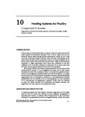
28 Pages • 12,905 Words • PDF • 388 KB

1 Pages • 157 Words • PDF • 36.6 KB

2 Pages • 399 Words • PDF • 299.6 KB

136 Pages • PDF • 78.5 MB

12 Pages • 2,397 Words • PDF • 365.8 KB

4 Pages • 297 Words • PDF • 72.9 KB

1 Pages • 120 Words • PDF • 22.8 KB

2 Pages • 1,233 Words • PDF • 263.3 KB

18 Pages • 3,619 Words • PDF • 57.8 KB

4 Pages • 105 Words • PDF • 8.2 MB